Download
1 / 5
50 likes | 191 Vues
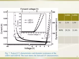
Fig. 7. Typical I-V characteristics and dynamic resistances of the LED-I and LED-II. The inset shows the forward I-V characteristics. Fig. 8. (a) Typical photograph of LED-I without current driving. (b) and (c) Typical near-field emission images of the LED-I and the LED-II, respectively.

E N D
Fig. 7. Typical I-V characteristics and dynamic resistances of the LED-I and LED-II. The inset shows the forward I-V characteristics. 9
Fig. 8. (a) Typical photograph of LED-I without current driving. (b) and (c) Typical near-field emission images of the LED-I and the LED-II, respectively. 10
Conclusion GaN-based blue LEDs using the InGaN insertion layer can effectively improve device performances including the endurance of ESD and light output power. The better current spreading effect is the dominant factor for contributing to the improvement of device performance. 11
References 維基百科 http://en.wikipedia.org/wiki/Nitrogen-vacancy_center 半導體技術天地 http://www.2ic.cn/html/82/t-326282.html 12