Download
1 / 36
390 likes | 618 Vues
Hall effect Sensors Variable Reluctance Sensor Ultrasonic Sensors (Sonic Distance Sensors) Photo Interrupt Pressure Sensors Accelerometers. Hall Effect Sensors. Hall Effect Sensor Sensing a Shaft Speed. Developed by Edwin Hall in 1879; and hence the name Hall effect Used to:

E N D
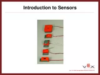
Hall effect Sensors Variable Reluctance Sensor Ultrasonic Sensors (Sonic Distance Sensors) Photo Interrupt Pressure Sensors Accelerometers
Hall Effect Sensors Hall Effect Sensor Sensing a Shaft Speed • Developed by Edwin Hall in 1879; and hence the name Hall effect • Used to: • provide noncontact means to detect and measure magnetic field http://farm1.static.flickr.com/62/227729006_fab88c1668.jpg?v=0
How they work Depiction principle of the Hall Effect • Presence of magnetic field deflects electrons flowing through conductive material • As electrons move to one end of conductive material: • Potential is developed in direction perpendicular to gross current flow • Potential indicates strength of magnetic field http://upload.wikimedia.org/wikipedia/commons/a/ab/Hall_effect_A.png
Applications • IC Engine Electronic Ignition Systems • Used to determine position of cam shaft • Brushless DC Motor Control • Sensors determine position of permanent magnet rotor • Assembly Lines • To determine shaft position and velocity • As contactless limit switches • Current Sensing ICs • Electrically isolated alternative to shunt resistors
Hall Effect Sensor Types • Linear Hall Effect Sensors • Output is proportional to magnetic field strength • Hall Effect Digital Switches • Presence of magnetic field above threshold turns switch on • Presence of magnetic field below threshold turns switch off • Hall Effect Digital Latches • North field turns latch on • South field turns latch off
Packaging and Manufacturers • ICs • Analog Devices: • AD22151G from Analog Devices • Allegro MicroSystems, Inc. • Wide range of linear, latching and switching sensors • Great sampling policy • Many, many more • Packaged units • Honeywell • Many, many more SOT23 SIP http://www.allegromicro.com/en/Products/Part_Numbers/1120/pinout.gif Hall Effect Sensor Module http://sensing.honeywell.com/client_asset/document/1/5/4/0/3/5/document_C3697B35-C930-CB7C-FE090DFFCE61FB22.jpg
Implementation and Words of Warning • Sensors may be affected by temperature variation. • Some sensors incorporate circuitry to reduce this error. • Sensors may be directional: • Care must be taken with respect to orientations of sensor and magnet • Some Hall Effect sensors detect presence of ferromagnetic materials, not magnetic fields
Variable Reluctance Sensors Industrial Variable Reluctance Sensor • Used to measure speed and/or position of moving metallic object • Sense change of magnetic reluctance(analogous to electrical resistance) near sensing element • Require conditioning circuitry to yield a useful signal (e.g. LM1815 from National Semi.) http://www.motionsensors.com/railwithoring2.jpg
How Variable Reluctance Sensors Work • Magnet in sensor creates magnetic field • As ferrous object moves by sensor • Resulting change in magnetic flux induces emf in pickup coil Typical Configuration Variable Reluctance Sensor Construction http://www.instronics.com/images/sensoronix/image.ds.drawing.vr.jpg
Typical Application • Shaft velocity sensor for ABS/traction control • Crank and cam shaft position sensors Installed on CV axle Sensor Schematic http://www.me.gatech.edu/mechatronics_lab/Projects/Spring07/Group1/dorthy6.JPG
Interfacing Concerns • Emf is proportional to rate of change of magnetic flux. • Dictates ferrous material must be moving for sensor to generate signal. • Output voltage is dependent on velocity of toothed wheel • Performance may be reduced at slow speeds
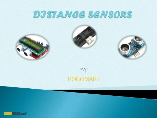
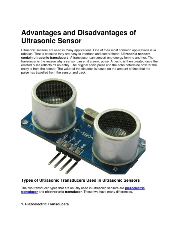
Ultrasonic Transducer • Ultrasonic transducer (piezoelectric transducer) is device that converts electrical energy into ultrasound • Upon receiving sound echo (pressure wave) back from surface, ultrasound transducer will turn sound waves into electrical energy which can be measured and displayed • Ultrasound are sound waves above normal range of human hearing (greater than 20K hertz).
Since piezoelectric crystal generates voltage when force is applied to it, same crystal can be used as an ultrasonic generator and detector • Some systems use separate transmitter and receiver components while others combine both in single piezoelectric transceiver • Alternative methods for creating and detecting ultrasound include magnetostriction and capacitiveactuation. Pulse echo sensor Transmit-Receive sensor
Sound is transmitted through propagation of pressure in air • Speed of sound in air is normally 331 m/sec at 0oC and 343 m/sec at 20oC for dry air • Digital signal processor embedded in sensor calculates distance between sensor and object
X = vsound . t • Where: • Vsound is known • t = 0.5 (time of flight) • X is distance between sensor head and object • Range of sensor varies between 5 cm to 20 m • Sensor is not appropriate for very short distance measurements • Frequency response (distance measurement update rate) varies with distance measured • In general, it is about 100 Hz
Piezoelectric crystals have property of changing size when voltage is applied • Applying alternating current (AC) across them causes them to oscillate at very high frequencies • Producing very high frequency sound waves • Ultrasonic sensors work on principle similar to radar or sonar • Radar and Sonar evaluate attributes of target • Interpreting echoes from radio or sound waves respectively
Applications • Medical: • Medical ultrasonic transducers (probes): • Come in variety of different shapes and sizes for use in making pictures of different parts of body • Transducer may be: • Passed over surface of body or • Inserted into body openingsuch as rectum or woman’s reproductive organ • Clinicians who perform ultrasound-guided procedures often use probe positioning system to hold the ultrasonic transducer.
Technology can be used for measuring: • wind speed and direction (anemometer), • speed through air or water • fullness of tank • amount of liquid in tank • sensor measures distance to surface of fluid. • Other applications include: • in robots for obstacle avoidance • burglar alarms • non-destructive testing, and etc
Laser Ultrasound System Control Box Nd:YAG Laser EMAT and Preamp Positioning Axis-lead screw Data Acquisition and User Interface • Nd:YAG pulsed laser: • Repetition rate: 20 Hz • Pulse Width: 10 ns • Pulse Energy: 45-450 mJ/pulse • Beam Diameter: 6 mm • Positioning Stage: • Resolution: 50 μm • Electro-Magnetic Acoustic Transducer (EMAT): • Bandwidth: 200 kHz-2.5 MHz • Data Acquisition Card: • Resolution: 14 bit • Sampling Rate: 125 MHz
Automated Weld Inspection System System consists of laser, beam delivery subsystem, stepper motor driven linear screw, electromagnetic acoustic transducer (EMAT), data acquisition card, computer software, and control unit Generated ultrasounds traveling through weld seams are received by EMAT System resolution not yet determined, but has been used to detect 0.4 mm void Used system to inspect 180 mm long weld bead at 1 mm increment in 26 secs Type of defects: Lack of penetration; Blow hole; and Short leg Mirror 3 Lens Mirror 2 Beam Delivery Sample Incident Laser Beam EMAT Mirror 1 EMAT Linear Screw Laser Preamp
Identifications of Solder Bump Defects in Chip Packages Flip Chip Chip Scale Package 3-D Packaging: Stacked Die Examples of Emerging Microelectronic Packages: Quad Flat Package (QFP) Total Bumps: 560 Ball Grid Array (BGA) Amkor Super BGA
Optical Micrographs of Good and Bad Solder Bump Cross Sections Good Solder Bump Head-in-Pillow defects Poor wetting, an intermittent connection • Two medium size voids near the interface
Optical micrographs of Good and Bad Solder Bump Cross Sections Crack initiates at the edge of the pad Pad crater with crack initiating at the trace • Inspection of solder bumps is crucial process in microelectronics manufacturing industry.
Intelligent Laser Ultrasound Inspection System • Laser Beam Delivery: • High-quality fiber face polish with fiber injection optics • Stable laser injection optical mount • Rugged, rubber/metal fiber jacketing • Variable excitation spot (0.6-8.0 mm2) • Excitation standoff distance > 50 mm • Fiber-coupled sensor head • 16 mm aperture • 3 μm minimum spot diameter • Variable standoff distance via autofocus system • DVT SmartImage Sensor • PC programmable stand-alone image processing sensor • Fiducial coordinates sent to PC through serial port • 640 x 480 pixel resolution, 8–bit grayscale CCD • 1/10 th pixel software resolution, 5 mm viewing window • Possible sub-micron resolution Model: New Wave Research Polaris II Wavelength: 1064 nm or 532nm with SHG Repetition Rate:1~20 Hz variable Pulse Width: 4-5 ns Pulse Energy: 45mJ/pulse, optical attenuator adjustable B C A D • Typical Data Acquisition Parameters • Sampling rate: 25 MHz @ 12-Bit res. • Trigger source: Laser output • Sample depth: 2048 samples (~ 82 μsec @ 25 MHz) • Voltage Range: ±100 mV (~ ±5 nm) • Signal Averaging: 4–128 avgs. E • High stiffness, preloaded bearings • Integral X/Y table designed with wide base to increase stiffness • Higher bidirectional repeatability (< ±6 μm,) • Larger mounting surface (326 x 326 mm) • Larger travel (200 x 200 mm) F • Stiff, pre-loaded linear motion components • Linear encoder measurement (1μm res.) • High precision (±10 μm) G • Polytec Laser Doppler Vibrometer • Heterodyne interferometer capable of displacement measurements • 50 nm/Volt analog output • 150 nm full scale output (peak to peak) • Operating Frequency Range: 50 kHz to 25 MHz • Lower cutoff frequency: 25 kHz (-3 dB), rolloff 40 dB/dec H • Vibrometer Autofocus System • Hands free autofocus system to increase repeatability and throughput • Customizable focusing algorithms for different kinds of chip package • Remote operable • Serial interface with MATLAB for fully automated testing • Average refocus time: 3 sec I
Laser Ultrasound Inspection (LUI) System 3 US Patents Have Been Issued & 2 Pending
Photo Interrupt • Uses emitter and detector photo diode pair • With no obstruction detector is high • When an object blocks the light the detector is low • Advantages • Simple to interface • Inexpensive • Reliable
Photo InterruptTypes • Wide variety of packages and orientations • Types • Logic (digital ±5 volts) • Transistor/diode (analog) • Manufacturers • Fairchild • Honeywell
Photo InterruptApplications • Encoder wheel for angular measurements. • Computer mouse with a ball
Photo InterruptApplications • Detect holes or slots for positioning of liner slides • Elevators • Detect the location of products on and assembly line
Pressure Sensors • Used to detect pressure of fluids or gasses. • Technologies (many) • Strain gage • Piezoresistive • Microelectromechanical systems (MEMS) • Each sensor has a pressure range that it works in. • Most have analog outputs that need amplification • Some have built-in amplifiers for direct connection into microcontroller
Pressure SensorsTypes • Differential Pressure • Difference between two or more pressures introduced as inputs to the sensing unit • 2 input • Absolute/Gage Pressure • The pressure relative to perfect vacuum pressure or set pressure (like pressure at sea level) • 1 input
Pressure SensorsApplications • Measure pressure of gas or fluids • Measure altitude • For plains or weather balloons • Measure flow • pressure sensors in conjunction with the venturi effect to measure flow • Measure depth of water • When measuring liquids, most sensors are not rated to have unclean liquids contact the sensor components. A small amount of air in the tube right before the sensor will create a barrier from the liquid.
Accelerometers • Used to measure acceleration • Common SI units meters/second2 (m/s2) or popularly in terms of g-force (1 g is earth’s gravity) • At rest an acceleration will measure 1 g in the vertical direction • They can come in 1, 2 or 3 axis configurations • With 3 axis it gives a vector of the accelerations direction (after accounting for gravity)
Accelerometers • Because of earth’s gravity, the sensor will read 1 to 0 g as the sensor is rotated from being vertical to horizontal. • This can be used to measure angle the of tilt • Each sensor has a range that it works in. • Most have analog outputs that need amplification • Some have built-in amplifiers for direct connection into microcontroller
AccelerometersHow they work • Mechanically the accelerometer behaves as a mass-damper-spring system • Many use Microelectromechanical systems (MEMS). Which use very small cantilever beams with masses on them • Under the influence of gravity or acceleration, the proof mass deflects from its neutral position. • This deflection is measured in an analog or digital manner • Commonly the capacitance between a set of fixed beams and a set of beams attached to the proof mass is measured. • Integrating piezoresistors in the springs to detect spring deformation is another method
AccelerometersApplications • Can be used to sense orientation, vibration and shocks. • Used in electronics like the Wii and iPhone for user input. • Acceleration integrated once gives velocity, integrated a second time gives position. • The integration process is not precise and introduces error into the velocity and position.