Download
1 / 32
320 likes | 464 Vues
A Smart Port Card (SPC and SPC-II) Tutorial --- Hardware John DeHart Washington University jdd@arl.wustl.edu http://www.arl.wustl.edu/~jdd. Motivation. Active Networking Network Probe High performance router architectures PC as router is VERY limited

E N D
A Smart Port Card (SPC and SPC-II) Tutorial --- Hardware John DeHart Washington University jdd@arl.wustl.edu http://www.arl.wustl.edu/~jdd
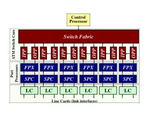
Motivation • Active Networking • Network Probe • High performance router architectures • PC as router is VERY limited • (Gigabit/s + Processing) on each port • MSR: Multi-Service multiport Router
The Original Smart Port Card • Hardware: • SPC as a PC • How do they each boot? • SPC Hardware Components • What roles do they play?
Typical Pentium PC CPU/Memory Bus Addr/Data Ctrl Ctrl Cache CPU North- Bridge DRAM Addr/Data/Ctrl PCI Bus Intr NMI INIT SouthBridge (PIIX3) (PIC, PIT, …) PCI Devices ISA Bus ISA Devices Super-IO BIOS BIOS RTC Uarts Kbd/Mse Floppy Parallel ...
Typical Pentium PC: CPU/Memory Bus CPU/Memory Bus Addr/Data Ctrl Ctrl Cache CPU North- Bridge DRAM Addr/Data/Ctrl PCI Bus Intr NMI INIT SouthBridge (PIIX3) (PIC, PIT, …) PCI Devices ISA Bus ISA Devices Super-IO BIOS BIOS RTC Uarts Kbd/Mse Floppy Parallel ...
Typical Pentium PC: PCI Bus CPU/Memory Bus Addr/Data Ctrl Ctrl Cache CPU North- Bridge DRAM Addr/Data/Ctrl PCI Bus Intr NMI INIT SouthBridge (PIIX3) (PIC, PIT, …) PCI Devices ISA Bus ISA Devices Super-IO BIOS BIOS RTC Uarts Kbd/Mse Floppy Parallel ...
Typical Pentium PC: ISA Bus CPU/Memory Bus Addr/Data Ctrl Ctrl Cache CPU North- Bridge DRAM Addr/Data/Ctrl PCI Bus Intr NMI INIT SouthBridge (PIIX3) (PIC, PIT, …) PCI Devices ISA Bus ISA Devices Super-IO BIOS BIOS RTC Uarts Kbd/Mse Floppy Parallel ...
How NetBSD Boots on a PC Components: • Pentium • Boot ROM (part of BIOS in modern systems?) • BIOS • Bootloader • Kernel
Sketch of How a PC Boots • Pentium after Reset: • fetches its first instruction from location 0xFFFFFFF0 • Boot Code must be located at 0xFFFFFFF0 • Boot Code jumps to BIOS located in ROM • Boot Code may actually be part of the BIOS... • BIOS copies itself into memory (Shadow) • BIOS remaps memory • future accesses to BIOS addresses go to memory instead of ROM. • BIOS performs system configuration (some proprietary) • Motherboard Details • Pentium Details • NB/SB Chipset Details • Device configuration: IRQs, Memory maps, ...
How a PC Boots (continued…) • BIOS loads bootloader into memory (from disk…) • BIOS jumps to bootloader • Bootloader performs some more configuration: • Pentium control registers • Cache configuration • Memory/Page model • Bootloader determines what to run next. • Bootloader may have to do some device configuration. • e.g. to get OS from a disk. • Bootloader loads OS kernel into memory • Bootloader jumps to start of OS kernel • Kernel does some OS-specific configuration: • for NetBSD look in: sys/arch/i386/i386/locore.s • Determines what CPU it has (“cpuid” instruction) • Paging • Virtual Memory
Typical Pentium PC (Again…) CPU/Memory Bus Addr/Data Ctrl Ctrl Cache CPU North- Bridge DRAM Addr/Data/Ctrl PCI Bus Intr NMI INIT SouthBridge (PIIX3) (PIC, PIT, …) PCI Devices ISA Bus ISA Devices Super-IO BIOS BIOS RTC Uarts Kbd/Mse Floppy Parallel ...
Addr/Data Ctrl Ctrl Cache CPU North- Bridge DRAM Addr/Data/Ctrl PCI Bus Intr NMI INIT SouthBridge (PIC, PIT, …) APIC BIOS BIOS RTC Uarts What SPC Needs CPU/Memory Bus
Addr/Data Ctrl Ctrl Cache CPU North- Bridge DRAM Addr/Data/Ctrl PCI Bus Intr NMI INIT SouthBridge (PIC, PIT, …) APIC BIOS BIOS RTC Uarts What SPC Needs: CPU/Memory Bus CPU/Memory Bus
Addr/Data Ctrl Ctrl Cache CPU North- Bridge DRAM Addr/Data/Ctrl PCI Bus Intr NMI INIT SouthBridge (PIC, PIT, …) APIC BIOS BIOS RTC Uarts What SPC Needs: PCI Bus CPU/Memory Bus
Addr/Data Ctrl Ctrl Cache CPU North- Bridge DRAM Addr/Data/Ctrl PCI Bus Intr NMI INIT SouthBridge (PIC, PIT, …) APIC BIOS BIOS RTC Uarts What SPC Needs: ISA Bus? CPU/Memory Bus
Intel Embedded Module UART1 UART2 System FPGA SPC Architecture Addr/Data Ctrl Ctrl Cache CPU North- Bridge DRAM Addr/Data/Ctrl PCI Bus NMI INIT Intr APIC RTC’ PIC PIT UART1 Interface BIOS ROM Link Interface UART2 Interface Switch Interface
SPC Components • APIC • Pentium Embedded Module • 166 MHz MMX Pentium Processor • L1 Cache: 16KB Data, 16KB Code • L2 cache: 512 KB • NorthBridge - 33 MHz, 32 bit PCI Bus • System FPGA • Xilinx XC4020XLA-1 FPGA • Memory • EDO DRAM: 64MB (Max for current design) • SO DIMM • Switch and Link Interfaces – Each 1 Gb Utopia • UART supports two Serial Ports: • NetBSD system console • TTY port
System FPGA • Coded in VHDL • PCI slave device • Replaces some of the PIIX3 (south bridge) • Replaces some of the BIOS • Replaces some of the Super IO Chip • Provides reset capability
System FPGA: PIIX3 Functionality • Programmable Interrupt Controller (PIC) • Four Interrupts supported and statically assigned: • PIT (IRQ 0) • APIC (IRQ 5) • COM1 (IRQ 4) • COM2 (IRQ 3) • Static fully-nested interrupt priority structure. • Specific End of Interrupt is the only EOI mode supported • Programmable Interval Timer (PIT) • generates a clock interrupt for NetBSD every ~10ms • Reset - covered in a later slide
System FPGA: BIOS Functionality • Interrupt functionality replaced by static values • Simple 16 word by 32-bit “ROM” • implements loop waiting for location 0xFFE00 to change value • then jumps to boot loader code • Does NOT perform configuration of Northbridge • This will be done by the boot loader • Does NOT perform PCI configuration of APIC • This will be done by the APIC Driver
System FPGA: Super IO Chip Functionality • UART Interface • Two Serial lines supported • Fixed IRQs • Real Time Clock • only the register accesses of the RTC are supported • no interrupts supported • i.e. supported only so NetBSD didn’t need to change • i.e. no alarms will be generated
System FPGA: Reset • SPC needs a reset before every download: • switch reset: • causes SPC to be reset • causes all connections in switch to be lost • System FPGA reset • causes SPC to be reset • has no effect on the switch • Normal SouthBridge reset: • I/O Register: 0xCF9 • Hard Reset: assert CPURST, PCIRST#, and RSTDRV • write 0xCF9 0x02 (00000010b) • write 0xCF9 0x06 (00000110b) • Soft Reset: assert INIT • write 0xCF9 0x00 (00000000b) • write 0xCF9 0x04 (00000100b) bits
System FPGA: Reset • SPC Reset: • a sequence of two writes to memory addresses • APIC Control cells can write to • memory addresses • configuration registers • NOT I/O Registers! Argh... • To mimic the reset structure of the SB we use: • 0xFFFFFFF0 • 0xFFFFFFF4 • Hard Reset (all we really care about) • write 0xFFFFFFF0 0x02 (00000010b) • write 0xFFFFFFF4 0x06 (00000110b) bits
References: SPC-I (on Kits Web Pages) • Intel Embedded Module: • Data Sheet • Design Guide • 430HX Chipset • NorthBridge • SouthBridge • System FPGA • Memory • Mobile Pentium with MMX • Software Developer Manuals 1,2,3 • Datasheet • APIC • Cache
SPC-II • Motivation • Faster Processor • More Memory • Faster Memory Bus • Simpler • Real BIOS • No System FPGA to build a fake Southbridge • Interchangeable modules • 700 MHz already available • Other low-power modules also available • You can buy new/faster CPU modules if you want… • More details to be given by Dave Richard on Tuesday at the Workshop
ETX Embedded Module SPC-II Architecture AGP Bus DRAM Video Video DB15 IDE Bus FLASH DISK I/O P-III CPU North- Bridge South- Bridge Keyboard Mouse BIOS Serial Ports ISA Bus PCI Bus APIC FPGA Switch Interface Link Interface
IPP OPP 500/700 MHz Pentium-III 256 KB L2 Cache SPC-II Architecture SWITCH BIOS ISA Devices 256 MB SDRAM FPX Super-IO ISA Bus South Bridge 32 bit 16 bit FPGA Port 1 APIC Port 0 Intel BX North Bridge PCI BUS 100 MHz Memory Bus 16/32 bit 16 bit SPC-II TI Link
SPC-II • Components • Intel Module • 500 MHz Pentium III • 256 KB L2 Cache • Northbridge and Southbridge • 33 MHz, 32 bit PCI Bus • 100 MHz memory bus • BIOS • Video, Mouse, Keyboard • APIC • FPGA: for ATM level routing • Extra PCI Slot: Debugging possibilities. • 256 MB of Memory • 32 MB IDE DOM (Disk On Module) • right now holds binary boot code • could later hold actual kernel • larger ones are possible
Booting an SPC-II • IDE DOM contains boot code • modified Stage2 from AAL5_download • configured to boot in place of a kernel • No special BIOS tricks to play • contains APIC code to put kernel into memory • kernel downloaded via AAL5 frames • uses Stage3 from AAL5_download • kernel booted when download complete
SPC II FPGA Architecture PCI Bus Port APIC Port 0 Port 1 OSC Reset VPI[0]=1 VCI = 38 VPI[0]=1 VPI[0]=0 64<=VCI<=127??? Switch LC FPX SPC-II FPGA
SPC-II References and more info • APIC References the same as before • Other references to come soon • Dave Richard will talk more about SPC-II on Wednesday at the Workshop