Electron Optics
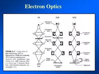
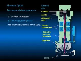
Electron Optics Transmission Electron Microscope Optical instrument in that it uses a lens to form an image Scanning Electron Microscope Not an optical instrument (no image forming lens) but uses electron optics. Probe forming-Signal detecting device. Electron Optics


Electron Optics
E N D
Presentation Transcript
Transmission Electron Microscope Optical instrument in that it uses a lens to form an image Scanning Electron Microscope Not an optical instrument (no image forming lens) but uses electron optics. Probe forming-Signal detecting device.
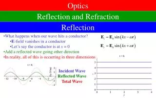
Electron Optics Refraction, or bending of a beam of illumination is caused when the wavelength enters a medium of a different optical density.
Electron Optics In light optics this is accomplished when a wavelength of light moves from air into glass In EM there is only a vacuum with an optical density of 1.0 whereas glass is much higher
Electron Optics In electron optics the beam cannot enter a conventional lens of a different optical density. Instead a “force” must be applied that has the same effect of causing the beam of illumination to bend.
Electron Optics In electron optics the beam cannot enter a conventional lens of a different optical density. Instead a “force” must be applied that has the same effect of causing the beam of illumination to bend. Electromagnetic Force or Electrostatic Force
Classical optics: The refractive index changes abruptly at a surface and is constant between the surfaces. The refraction of light at surfaces separating media of different refractive indices makes it possible to construct imaging lenses. Glass surfaces can be shaped. 2) Electron optics: Here, changes in the refractive index are gradual so rays are continuous curves rather than broken straight lines. Refraction of electrons must be accomplished by fields in space around charged electrodes or solenoids, and these fields can assume only certain distributions consistent with field theory.
Converging (positive) lens: bends rays toward the axis. It has a positive focal length.
Diverging (negative) lens: bends the light rays away from the axis. It has a negative focal length. An object placed anywhere to the left of a diverging lens results in an erect virtual image. It is not possible to construct a negative magnetic lens although negative electrostatic lenses can be made
Electron Optics Electrostatic lens Must have very clean and high vacuum environment to avoid arcing across plates
Electron Optics Electrostatic lens Converging Lens Diverging Lens
Electromagnetic Lens Passing a current through a single coil of wire will produce a strong magnetic field in the center of the coil
Electromagnetic Lens Pole Pieces of iron Concentrate lines of Magnetic force
The two force vectors, one in the direction of the electron trajectory and the other perpendicular to it, causes the electrons to move through the magnetic field in a helical manner.
The strength of the magnetic field is determined by the number of wraps of the wire and the amount of current passing through the wire. A value of zero current (weak lens) would have an infinitely long focal length while a large amount of current (strong lens) would have a short focal length.
A TEM image is made up of nonscattered electrons (which strike the screen) and scattered electrons which do not and therefore appear as a dark area on the screen
Some of the scattered electrons will only be partially scattered and thus will reach the screen in an inappropriate position giving a false signal and thus contributing to a degradation of the image. These forward scattered electrons can be eliminated by placing an aperture beneath the specimen.
The design of an electromagnetic lens results in a very strong lens with a very short focal length thus requiring that the specimen lie within the lens itself along with an aperture to stop the highly scattered electrons
Upper Pole Piece Specimen Aperture Lower Pole Piece Both the specimen rod and the aperture rod assembly have to be inserted into the lens. They are made of nonmagnetic metals such as copper, brass, and platinum
While a small opening objective aperture has the advantage of stopping scattered electrons and thus increasing image contrast it also dramatically reduces the half angle of illumination for the projection lenses and thus decreases image resolution
Lens Defects Since the focal lengthf of a lens is dependent on the strength of the lens, if follows that different wavelengths will be focused to different positions. Chromatic aberration of a lens is seen as fringes around the image due to a “zone” of focus.
Lens Defects In light optics wavelengths of higher energy (blue) are bent more strongly and have a shorter focal length In the electron microscope the exact opposite is true in that higher energy wavelengths are less effected and have a longer focal length
Lens Defects In light optics chromatic aberration can be corrected by combining a converging lens with a diverging lens. This is known as a “doublet” lens
Lens Defects A few manufacturers have combined an electromagnetic (converging) lens with an electrostatic (diverging) lens to create an achromatic lens LEO Gemini Lens
The simplest way to correct for chromatic aberration is to use illumination of a single wavelength! This is accomplished in an EM by having a very stable acceleration voltage. If the e velocity is stable the illumination source is monochromatic
The problem arises when electrons are differentially scattered within the specimen slowing some more than others and thus producing poly-chromatic illumination from a monochromatic beam.
The effects of chromatic aberration are most profound at the edges of the lens so by placing an aperture immediately after the specimen chromatic aberration is reduced along with increasing contrast
Lens Defects The fact that wavelengths enter and leave the lens field at different angles results in a defect known as spherical aberration. The result is similar to that of chromatic aberration in that wavelengths are brought to different focal points
Spherical aberrations are worst at the periphery of a lens so again a small opening aperture that cuts off the most offensive part of the lens is the best way to reduce the effects of spherical aberration
Diffraction Diffraction occurs when a wavefront encounters an edge of an object. This results in the establishment of new wavefronts
Diffraction When this occurs at the edges of an aperture the diffracted waves tend to spread out the focus rather than concentrate them. This results in a decrease in resolution, the effect becoming more pronounced with ever smaller apertures.
Apertures Disadvantages -Decrease resolution due to effects of diffraction -Decrease resolution by reducing half angle of illumination -Decrease illumination by blocking scattered electrons Advantages -Increase contrast by blocking scattered electrons -Decrease effects of chromatic and spherical aberration by cutting off edges of a lens
If a lens is not completely symmetrical objects will be focussed to different focal planes resulting in an astigmatic image
The result is a distorted image. This can best be prevented by having as near to perfect a lens as possible but other defects such as dirt on an aperture etc. can cause an astigmatism
Astigmatism in light optics is corrected by making a lens with a corresponding defect to correct for the defect in another lens In EM it is corrected using a stigmator Which is a ring of electromagnets positioned around the beam to “push” and “pull” the beam to make it more perfectly circular