Download
1 / 12
140 likes | 322 Vues
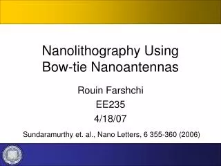
Nanolithography Using Bow-tie Nanoantennas. Rouin Farshchi EE235 4/18/07. Sundaramurthy et. al., Nano Letters, 6 355-360 (2006). Near-field optics and Nanoantennas Nanolithography Bow-tie nanoantennas - lithography - FDTD modeling Summary. Outline.

E N D
Nanolithography UsingBow-tie Nanoantennas Rouin Farshchi EE235 4/18/07 Sundaramurthy et. al., Nano Letters, 6 355-360 (2006)
Near-field optics and Nanoantennas Nanolithography Bow-tie nanoantennas - lithography - FDTD modeling Summary Outline 2
Near-field Optics Sanchez, PRL 82, 4014 (1999) Near-field: immediate vicinity of “light source” with dimensions < l. Near-field Probes: Sharp tips (ANSOM), coated tapered optical fibers (NSOM) Nanoantennas: plasmon resonance coupling Nanopartice arrays, Pairs of nanoparticles Hecht, JPC 112, 7761 (2000) Produce greatly enhanced fields upon laser excitation (up to 103), confined to regions ~20nm, significantly defeating diffraction limits: microscopy, SERS, lithography ~ 300 nm Rechberger, Opt. Comm. 220 (2003) 137–141 3
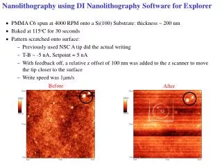
Near-field optical lithography • Achieve ~ l / 10 resolution by focusing femtosecond laser beam • onto Au coated AFM tip in close proximity to SU-8. • Two-photon polymerization occurs in SU-8 over confined regions • due to local enhancement of electric field by surface plasmons on AFM tip. Yin et. al., Appl. Phys. Lett. 81 3663 (2002) 4
Bow-tie Nanoantennas 103 field enhancement to <30 nm regions 10% efficiency (define) vs ~10-5 for NSOM • Effects: • Plasmon resonance in each triangle • Coupling across gap Au triangles on ITO (fabrication in [1]) Finite difference time domain (FDTD) for computation of [3]: - intensity enhancement - scattering efficiency - resonant wavelengths - ~103 enhancement of incident intensity - confined to 650 nm2 region [1] Schuck et al., Phys. Rev. Lett. 94, 017402 (2005) [2] Fromm et al., Nano Lett. 4, 957 (2004) 5 [3] Sundaramurthy et al., Physical Rev. B, 72 165409 (2005)
Au ~80 nm 16 - 40 nm SU-8 ~75 nm Au ~20 nm ~4 nm Ti sticking layer ITO substrate Bow-tie Fabrication Define with e-beam lithography Measured with TPPL [Schuck] Sundaramurthy et al., Nano Letters, 6 355-360 (2006) 6 Schuck et al., Phys. Rev. Lett. 94, 017402 (2005)
SU-8 Exposure of SU-8 on bowties Exposure powers: 27mW – 10 mW Focus beam to diffraction-limited spot With 1.3 NA 100x obvective lens polarizer, beam-splitter Excitation source: Ti:sapphire laser 120 fs, f = 75 MHz l = 800 nm Measured with TIR microscopy Sundaramurthy et al., Nano Letters, 6 355-360 (2006) 7 Sundaramurthy et al., Physical Rev. B, 72 165409 (2005)
AFM / SEM of exposed SU-8 Nano-lithography: - Exposure + develop, bow-tie nanoantennas covered with SU-8 AFM: At high exposure powers, SU-8 ablation at bow-ties SU-8 TPP away from bow-ties TPP only at bow-tie gap Blanket TPP No TPP TPP in vicinity of bow-tie Sundaramurthy et al., Nano Letters, 6 355-360 (2006) 8
AFM of exposed SU-8 Nano-lithography: - Exposure + develop, bow-tie nanoantennas covered with SU-8 • Au bow-ties “capture” energy of diffraction limited spot and concentrate it at two small areas near the gap, exceeding exposure threshold. • record 30 nm features with near-field lithography using record low power of 27 mW Sundaramurthy et al., Nano Letters, 6 355-360 (2006) 9
Theory- FDTD displacement current in gap 16nm gap current in metal region 0.13 mA peak frequency dependant (RIT) far-field radiation power 500nm gap 0.05 mA peak scattering cross-section incident power scattering efficiency Sundaramurthy et al., Physical Rev. B, 72 165409 (2005) 10
Theory- FDTD The FDTD simulations predict an intensity enhancement of 107 at 4 nm above each of the triangle tips exposed at 27 mW, in good agreement with experimental value of 150 from experiment. FDTD Calculated enhancement peaks occur within 4 nm of SU-8 peak locations from AFM measurement. Sundaramurthy et al., Nano Letters, 6 355-360 (2006) 11
Conclusion - large electric-field enhancement in highly confined regions at tips of gold bow-tie nanoantennas - Allows for local exposure of SU-8 resist to record low dimensions (<30nm) using record low power (~27 mW) - Intensity enhancement thought to be due to coupling of plasmon resonance at tips of triangles, as suggested by theoretical modeling. Thank you! 12