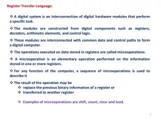
EKT 221 : Digital 2 HARDWIRE CONTROL
EKT 221 : Digital 2 HARDWIRE CONTROL. Hardwire Control. 2 Aspect in implementing Control Unit (CU): Control of microoperations(µO) Sequencing CU with µO Hence we divide ASM into 2 parts: CONTROL TABLE : Table that defines Control signal in terms of states & inputs


EKT 221 : Digital 2 HARDWIRE CONTROL
E N D
Presentation Transcript
Hardwire Control • 2 Aspect in implementing Control Unit (CU): • Control of microoperations(µO) • Sequencing CU with µO • Hence we divide ASM into 2 parts: • CONTROL TABLE : Table that defines Control signal in terms of states & inputs • SIMPLIFIED ASM : ASM Chart that only represents transitions from one state to another.
Control Table (Example for Binary Multiplier) 1 2 3 Table 8.1 : Morris Mano, pg 376
Control Table *Note : Parallel Adder & Zero Detect are microoperations Reg. B & Q need to be LOADED (IN) (Example for Binary Multiplier) 1 Table 8.1 : Morris Mano, pg 376
Analysis of ASM Chart with the Control Table. Write down all the operations corresponding to the hardware (FF, Registers and Counters) *Note : Reg. B & Q need to be LOADED (IN) 2
Analysis of ASM Chart with the Control Table. Write down all the operations corresponding to the hardware (FF, Registers and Counters) 2 *Note : Reg. B & Q need to be LOADED (IN)
3 • Register A include 3 microoperations: • Clear (A 0 ) • Add & load (A A + B) • Right shift (sr) • Since Clear operations always occurs at the same time as the clear of FF C and loading of counter P, all these uO can be activated by the same control : Initialize • However, C is also cleared in state MUL1 so we separate the control signal : Clear_C
3 • The Control Expression is determined by ASM chart. Since Initialize is 1 when G=1 and in state IDLE thus : IDLE . G • Clear_C : G=1, state IDLE, state MUL_1 so the Control Expression is IDLE . G + MUL_1 • Load and Shift_dec is define in similar manner • Once written, do not need to duplicate, so control expression is dashed “ – ” • Load_(reg) is loading the multiplier and multiplicand from outside input.
Simplified ASM Chart • Redraw the ASM Chart by removing the: • Microoperations • Conditional output • Condition box not affecting the next state • (Note : if the decision box is removed it goes to the same state)
Simplified ASM Chart Figure 8.9 : Morris Mano, pg377
Designing of CU • Procedure specializations that use a single signal to represent each state. • 2 methods: • Sequence Register and Decoder • Sequence register with encoded states • A reg. with n FF can have up to 2n states • e.g.(n=2); state = 22= 4 = 00, 01, 10, 11. • Decoder outputs produce “state” signals • An n-to-2n decoder has up to 2n outputs • e.g.(n=2); output = 2 to 4 = 0001,0010, 0100, 1000. • One Flip-flop per State • A FF is assigned to each states • Flip-flop outputs as “state” signals, e. g., 0001, 0010,0100, 1000. • And at any one time only one FF can be 1. • The single 1 propagates from one FF to another under control of decision logic.
Sequencer and Decoder Design (Binary Multiplier Example) • 2 inputs (G and Z) & 3 states (IDLE, MUL0 and MUL1) • 2 FF’s and 2 to 4 line decoder (only 3 states so only 3 out of 4 decoder output will be used) • From this info, construct the sequencing table
Constructing the Sequencing Table • First, define: • States: IDLE, MUL0, MUL1 • Input Signals: G, Z, Q0 (Q0 affects outputs, not next state) • Output Signals: Initialize, LOAD, Shift_Dec, Clear_C • State Transition Diagram (Refer to Simplified ASM Chart) • Output Function (Refer to Control Table) • Second, find • State Assignments (two bits required) • We will use two state bits to encode the three state IDLE, MUL0, and MUL1.
Constructing the Sequencing Table……cont. Assuming that state variables M1 and M0 are decoded into states, the next state part of the state table is: OR (refer to next slide) *NOTE : This method can be tedious if there are more FF’s in your design
Constructing the Sequencing Table……cont. We can derive directly from the ASM chart for input G and Z. Don’t care condition is designated as X
Extracting Equations From the table :- For M0 next state = 1 DMO = IDLE.G + MUL1.Z For M1 next state = 1 DM1 = MUL0
Extracting Equations • The output equations using the decoded states: • Initialize = IDLE · G • Load = MUL0 · Q0 • Clear_C = IDLE · G + MUL1 • Shift_dec = MUL1
Building the CU DMO = IDLE.G + MUL1.Z DM1 = MUL0 Initialize = IDLE · G Load = MUL0 · Q0 Clear_C = IDLE · G + MUL1 Shift_dec = MUL1 Draw your cct • Draw the decoder first with i/p from FF • Draw FF M0 and M1 i/p and o/p connecting to decoder (don’t forget your clock) • Draw o/p with coresponding i/p
Next Lecture • Designing CU using One FF per State