Download

1 / 9
90 likes | 182 Vues
Get insights into the redesigned high-voltage distribution boards & DAQ system enhancements for the GlueX experiment. Learn about troubleshooting past issues & future integration plans.

E N D
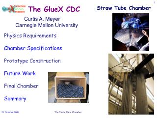
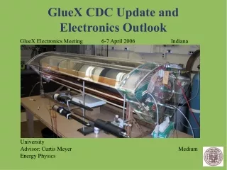
Michael McCracken Carnegie Mellon University Advisor: Curtis Meyer Medium Energy Physics GlueX CDC Update and Electronics Outlook GlueX Electronics Meeting 6-7 April 2006 Indiana University
Grad. student Zeb Krahn has been working to get the DAQ system full functional. I will talk about what components we have, and our current understanding of the DAQ system/CODA. Two main foci: Detector Hardware: High Voltage Distribution/Front-End Boards Electronics Hardware/DAQ System and CODA • The first boards I designed were bad... really bad. • In the next design, we have incorporated many of the features of the CLEO DR3 board. • Matt Shepherd, Paul Smith, and Gerard Visser have been immeasurably helpful in designing the new boards.
The First Distribution Boards Why were they so bad? • They were built on existing PCB's from another project. Thus, they had no ground plane and made the component configuration very awkward. • I tried to cram too many signals through the 34-pin connector in the plenum cover, thus eliminating the possibility of twisted pair cabling. • Overall, I made many rookie mistakes. How bad is bad? • There were horrible cross-talk and ringing problems in the signals. These boards were great antennae. • They offered limited compatibility with IU's pre-amp boards. Connectivity would have been a nightmare. Poorly designed front-end board, or expertly designed antenna? An average pulse, but can we trust it?
The New Boards • Matt pointed us in the direction of the CLEO DR3 boards. Our new design is very similar to these. • These new boards will be built on custom-fabricated PCB's, designed with Paul and Gerard's help. Features of the new boards include: • More compact and sensible board architecture. R0-4003 to eliminate out-gassing. • Large ground plane to provide more local and robust ground connection for paired output. These should help to control cross-talk and ringing. • The sense wire connections are made with co-ax cabling with the sheath held at bias voltage. • IU pre-amp boards will mate directly to the end of the distribution boards. Status: Right now we are looking for a fabrication company who offers the materials we need.
The Board in Some of It's Gory Detail: Interface to Pre-Amps Mount for HV connection Groundplane The new board is shown below. The groundplane is shown in grey, traces in blue, and a silkscreen layer is shown in red. Sense wire connections Connections to co-ax sheath Jumper for grounding/ biasing sheaths Hi-pass HV filters HV bus trace
Other foreseeable slowdowns • Fabrication turnaround, soldering/building... • Because the pre-amp boards mate directly to the HV boards, we will need to move them inside the plenum. We will have to fabricate some type of cooling system to take care of the pre-amp dissipation. (1 week?) Matt gave us some good ideas about how to do this. • Perhaps there will be some cabling issues in figuring out the most efficient way to rout the signal to all of the electronics.
The DAQ System We have been slowly gathering the pieces of a DAQ system to support the chamber. We now have: • Wiener VME Crate • 1 JLAB F1 TDC • 1 CAEN v792N ADC • JLAB Trigger Interface Board • MVME2600 Motorola PowerPC • LINUX node running CODA We are still waiting on the Struck sis3320, hopefully someone here has some info...
What are our present capabilities? • At the same time we realized that the previous HV distribution boards were useless, we were ready to take data with the ADC. • The ADC is ready at any time, and Zeb has written code to interpret the ADC output that we get from CODA. • Zeb is working to get the F1 TDC running with CODA. He has been talking with Dave Abbott about modifying the CODA readout lists to accept this. Should be working very soon. • As soon as the HV dist. boards are complete, we should be ready to look at cosmics with both TDC and ADC.
What happens next? • Hopefully, the new PCB's will be in our hands within 2-3 weeks. • We only need to equip 1 board to do meaningful tests with the chamber. Doing so shouldn't take much time. • F1 TDC should be becoming functional as we speak. Taking some data with it is a big priority. • Zeb will be finishing code in the next two weeks that interprets all of the CODA output. • Integrating the fADC when we get it... • Thanks again to Matt, Paul, and Gerard.