Download

1 / 33
350 likes | 1.41k Vues
Compact Heat Exchangers -- A New Approach. P.M.V Subbarao Associate Professor Mechanical Engineering Department Indian Institute of Technology, Delhi. Introductory Remarks.

E N D
Compact Heat Exchangers -- A New Approach P.M.V Subbarao Associate Professor Mechanical Engineering Department Indian Institute of Technology, Delhi
Introductory Remarks • Power, Process, Refrigeration and A/c and Aerospace industries require small size and light weight heat exchanger devices. • The size of heat exchanger is very large in those applications where gas is a medium of heat exchange. • Continuous research is focused on development of Compact Heat Exchangers --- High rates of heat transfer per unit volume. • The rate of heat exchange is proportional to • The value of Overall heat transfer coefficient. • The surface area of heat transfer available. • The mean temperature difference.
Overall Heat Transfer Coefficient and Thermal Resistance • In general the heat transfer coefficient of the gas may be 10 to 50 times smaller than that of the liquid. • In phase-change heat exchangers, the air side heat transfer often limits the thermal performance of heat exchangers. • The air side can comprise 75% of the thermal resistance in an evaporator and 95% in a condenser used in typical refrigeration applications. • In applications where the thermal resistance of one fluid dominates, significant cost reductions and energy savings can be achieved by using heat transfer augmentation devices or methods. • For this reason development of high-performance surfaces for air side heat transfer augmentation is an important area of interest.
Large surface area Heat Exchangers • The use of extended surfaces will reduce the gas side thermal resistance. • To reduce size and weight of heat exchangers, many compact heat exchangers with various fin patterns were developed to reduce the air side thermal resistance. • Fins on the outside the tube may be categorized as • 1) flat or continuos (plain, wavy or interrupted) external fins on arrays of tubes, • 2) Normal fins on individual tubes, • 3) Longitudinal fins on individual tubes. • Kays and London presented pressure drop and heat transfer characteristics of a wide variety of configurations of compact heat exchanger matrices.
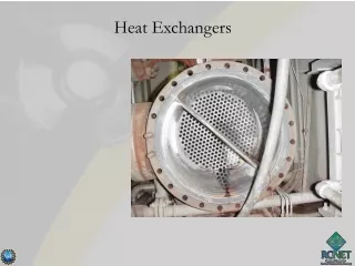
Fin and Tube Heat Exchanger : A primitive Compact Heat Exchanger
Liquid Flow Anatomy of Fin & Tube Heat Exchanger Gas Flow Plate Tube
Z dz (r+dr)d X dr r Two Dimensional Conduction In Cylindrical Coordinates System
Conduction Equation Local Heat Flux Vector: GDE for Steady State Temperature Distribution in Fin
Comments onConventional Compact Heat exchangers • Conventional compact heat exchangers were developed by increasing heat transfer surface area per unit volume of heat exchanger. • In spite of much larger heat transfer area the major part of thermal heat transfer resistance is due to gas side. • The potential for increasing the fin area is limited by the fact that the increasing fin area leads to drop in fin efficiency. • Major part of the fin area is wetted by low heat transfer coefficient gas flow. • large number of fins makes the system costlier, heavier, and spacious. • An attempt for having a broader vision on the enhancement of heat transfer coefficient is yet to be achieved.
Enhancement of Heat Transfer Coefficient • The magnitude of heat transfer coefficient is proportional to Reynolds number. • Huge increase in heat transfer coefficient is seen in turbulent flows when compared to laminar flows. • Turbulent flow is due to a combination of set of vortices (Eddies). • Recent research findings have shown that the vortices play an important role in enhancing the heat transfer. • At a given Reynolds number, the flow can be made more turbulent by introducing artificial vortices into the flow. • Artificial introduction of vortices on the gas side can be another potential alternative for augmenting heat transfer in compact heat exchangers.
Compact Heat Exchangers -- A New Concept • Creation of concept. • Testing and understanding of concept. • Explanation of the concept. • Discovery of various performance parameters of the concept. • Development of compact heat exchangers using the new concept. • Testing and performance evaluation. • Generation of Design data.
VORTEX GENERATORS • Wing type turbulators (a,b) • Winglet type turbulators (c,d) Thursday, 29 May, 2008 Mechanical Department, IIT Delhi 13
WINGLET VORTEX GENERATORS h: Height of trailing edge L: Base length β: Angle of attack X and Y: position coordinates with respect to center of tube t: Thickness of winglet AR: 2h/L, Aspect ratio Thursday, 29 May, 2008 Mechanical Department, IIT Delhi 14
VORTICAL DESCRIPTION OF FLOW PAST A DELTA WINGLET Thursday, 29 May, 2008 Mechanical Department, IIT Delhi 15
HEAT TRASNFER ENHANCEMENT BY WINGLET Thursday, 29 May, 2008 Mechanical Department, IIT Delhi 16
COMMON FLOW DOWN AND COMMON FLOW UP Top view Flow Flow (a) (b) Thursday, 29 May, 2008 Mechanical Department, IIT Delhi 17
z dz r.d r (r+dr)d dr x y Theory of circular fins Local heat Transfer Coefficient:
Measurement of Isotherms • Fifty thermocouples are embedded in central plate • The cylinder is electrically heated. • A special wind tunnel is designed developed and tested for this purpose. • Steady state temperature distribution is transferred to computer.
Positioning of Winglets around Tube • Objective is to raise to promote heat transfer rate in downstream of a tube. • High temperature gradients and heat transfer coefficients are to be created. • A placement of winglet also leads to raise in pressure drop. • An optimum location will produce a maximum heat transfer enhancement with low raise in pressure drop.
Main Observations • Mechanism of Heat Transfer Enhancement by Winglet • The winglet entrains more fluid into the downstream (wake) region and enhances fluid circulation. • This leads to increase in the value of local heat transfer coefficient and hence enhancement in the heat transfer rates in wake region. • Best winglet and best positions are those, which entrain more fluid into wake region.
Concluding Remarks • The winglet with = 1.33, located at X= 0.5D and Y=0.5D is the the option • The Result on prototype are encouraging. • The enhancement in heat transfer coefficient shows a great promise in reducing gas side thermal resistance. • Another effective alternate concept for construction of Compact Heat Exchangers. • Testing of real equipment and generation of final design procedure is our final goal.