Nano-Electronics and Nano-technology
200 likes | 517 Vues
Nano-Electronics and Nano-technology. A course presented by S. Mohajerzadeh, Department of Electrical and Computer Eng, University of Tehran. MOSFET Operation.

Nano-Electronics and Nano-technology
E N D
Presentation Transcript
Nano-Electronics and Nano-technology A course presented by S. Mohajerzadeh,Department of Electrical and Computer Eng,University of Tehran
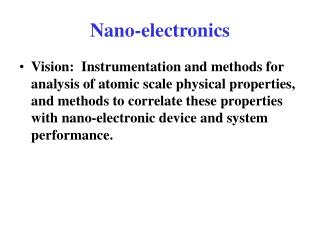
MOSFET Operation • MOSFET is a four-terminal device, where the application of gate voltage creates a layer of “opposite” carriers called as “inversion” layer. • The amount of inversion and the total number of carriers generated and built-up in the channel depends on the applied gate voltage. • The presence of a voltage between two other terminals (source and drain) leads to a flow of current from the source side onto the drain. • The amount of current depends both on VDS and VGS. After a certain value of VGS is passed (threshold voltage), the evolution of inversion layer is significant and current can flow between source and drain. • Increasing the drain voltage leads to “local” evacuation of the channel, called as pinch-off. • Further increase in the drain-source voltage will not have much effect in the current of the device (saturation regime). IDS=qCoxµeffW/L (VGS-VT)2 • µeff is the effective carrier mobility of the inversion layer and Cox is ε/tox. • For advanced devices, the electric permitivity must be high to allow the same amount of capacitance with a thicker oxide layer. Use of High “k” materials is inevitable!
Ballistic Transistors • When the dimensions of MOS devices shrink, the scattering of carrier through the channel reduces • Electrons can reach their ceiling velocity i.e. (2KT/πm*)1/2 where m* is the effective mass of electrons in the solid. • At room temperatures this speed equals 108 cm/s. • Operation of the device is essentially the same as a velocity saturation regime of MOSFET. • Quantum mechanics must be exploited to give a proper insight about the mechanism of transport in such devices.
Nano-scale MOSFET • When the dimensions becomes so small sub-bands evolve. • Each sub-band is a result of geometry reduction where the electron behaves as a particle in a box in two or one dimensions. • The limitation by Q-M leads to discrete values of momentum and corresponding energy levels. • In other directions, the behavior is more classic and variation can be considered small.
Nanoscale MOSFET • EC, conduction band • E1 and E2 two split sub-bands due to quantum confinement • E1 and E2 are constant, discrete energy levels of each state, • EC is modulated, due to non-equilibrium condition in the solid (assuming an ideal solid under external voltages)
Fermi distribution function, gives the probability of finding a particle at energy level “E”. • f(E)=(1+ exp ((E-Ef)/KT)))-1 ≈ exp (Ef-E)/KT • Considering the parabolic band structure (valid at low momentum’s) • f(E) = exp ((Ef – Ec + Ec –E)/KT) = exp ((Ef –Ec)/KT) exp (- ħ2 k2/2m*KT) = exp ((Ef –Ec)/KT) exp (- m*v2/2KT) • For a normal MOSFET device, the majority of carriers have velocities (energies) concentrated around zero and low enough (less than 107 cm/s)
Ballistic MOSFET • For small devices, the scattering is minimized and the extensive electric field leads to higher velocities in x-direction • Close to source, velocity shows a symmetrical distribution both in positive and negative direction, • At the top of the conduction band curve, the velocity is quite low. • At distances close to drain, the high speed peak (ballistic peak) is observed and in the drain, this situation becomes more significant.
Velocity saturation • In a standard MOSFET or under small biases, the velocity reaches its saturation limit and remains constant throughout channel. • By increasing the bias, the velocity overshoot is observed and ballistic peak is achieved.
Natori’s Theory • The positive k-states are populated by injectionfrom the source according to the source Fermi level, EF, and the negative k-states are populated from the drain according to the drain Fermi level,EF - qVDS. • VDS= 0, the positive and negative states are equally occupied, the average velocity is zero, and ID= 0. • For small VDS, the drain Fermi level is lowered, fewer negative k-states are occupied, the net velocity is positive. • For large VDS, the negative k-states are empty, the average velocity saturates at a value determined by thegate voltage, which determines the location of the Fermi level. • In this case the drain current saturates at the so-calledon-current. • ns+(Ef) – ns- (Ef-qVDS)= Q(0)/q ≈ Cox (VGS – VT) • This equation predicts the place of the Fermi level. The positive concentration is due to electrons flowing from source to drain and negative one is due to reverse flow.
Current Characteristics • I+(Ef) – I- (Ef-qVDS)= I(VDS) • Each electron travels with a speed of “v” which also depends on its energy. So, the total current depends both on velocity and density of the carriers. • I=qW( ns+(Ef) v+(Ef) – ns-(Ef-qVDS) v- (Ef –qVDS) ) • I= WQ(0) v+ (1 – (ns-/ns+)(v-/v+))/(1 + ns-/ns+)) • Gate voltage controls the value of Q(0) through electrostatic potential of the MOS structure.
Non-Degenerate case • ns+(0) = N2D/2 ( exp (Ef – E1(0))/KT)) • ns-(0) = N2D/2 (exp (Ef –qVDS – E1(0)/KT)) • I+=WJ+=Wqns+(0) v+ • I- = WJ- =Wqns-(0) v- • In the case of ballistic transport, v+=v- = vT= (2KT/m*π)1/2 • The final current: I=qWns(0) vT (1- exp (-qVD/kT))/(1+ exp (-qVD/KT) Where qns(0) = Cox(Vgs-VT)