Download
1 / 31
310 likes | 491 Vues
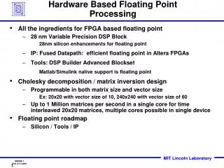
Area and Power Performance Analysis of Floating-point based Applications on FPGAs. Gokul Govindu, Ling Zhuo, Seonil Choi, Padma Gundala, and Viktor K. Prasanna Dept. of Electrical Engineering University of Southern California September 24, 2003. http://ceng.usc.edu/~prasanna. Outline.

E N D
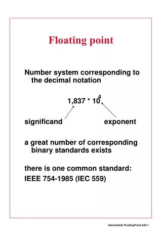
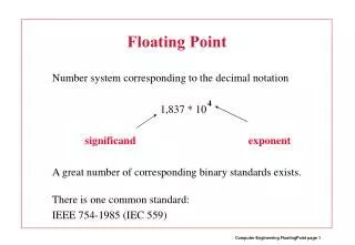
Area and Power Performance Analysis of Floating-point based Applications on FPGAs Gokul Govindu, Ling Zhuo, Seonil Choi, Padma Gundala, and Viktor K. Prasanna Dept. of Electrical Engineering University of Southern California September 24, 2003 http://ceng.usc.edu/~prasanna
Outline • Floating-point based Applications on FPGAs • Floating-point Units • Area/Power Analysis • Floating-point based Algorithm/Architecture Design • Area, Power, Performance analysis for example kernels: • FFT • Matrix Multiply • Conclusion
Floating-point based Applications on FPGAs Applications requiring • High numerical stability, faster numerical convergence • Large dynamic range Examples: • Audio/Image processing, Radar/Sonar/Communication, etc. Fixed-point vs. Floating-point • Resources • Slices • Latency/Throughput • Pipeline stages • Frequency • Precision • Design complexity of fixed/floating-point units Energy – Area – Performance Tradeoffs
Floating-point Device Options FPGAs (Virtex II Pro) More flexibility, Better performance per unit power High-performance Floating-point GPPs (Pentium 4) High-performance Floating-point DSPs (TMS320C67X) Performance Low-power Floating-point GPPs (PowerPC G4) Low-power Floating-point DSPs (TMS320C55X) Emulation by Fixed-point DSPs (TMS320C54X) Power
Need for FPU Design in the Context of the Kernel Integration • Latency • Number of pipeline stages as a parameter • Frequency • FPU frequency should match the frequency of the kernel/application’s logic • Area/Frequency/Latency tradeoffs Optimal Kernel Performance • High throughput • Maximize frequency • Minimize Energy • Architectural tradeoffs - FPUs parameterized in terms of latency/ throughput/ area • Optimize F/A for FPU • Maximize the performance of the kernel Algorithm/Architecture Design • Re-evaluation of the algorithm/architecture • Tolerate latencies of FPU - low area vs. high frequency tradeoffs • Re-scheduling
Outline • Floating-point based Applications on FPGAs • Floating-point Units • Area/Power Analysis • Floating-point based Algorithm/Architecture Design • Area, Power, Performance analysis for example kernels: • FFT • Matrix Multiply • Conclusion
Our Floating-point Units • Now, easier to implement floating-point units on FPGAs • Optimized IP cores for fixed-point adders and multipliers • Fast priority encoders, comparators, shift registers, fast carry chains…. Our floating-point units • Precision • Optimized for 32, 48 and 64 bits • IEEE 754 format • Number of pipeline stages • Number of pipeline stages parameterized • For easy integration of the units into the kernel • For a given kernel frequency, units with optimal pipelining and thus optimal resources, can be used • Metrics • Frequency/Area • Overall performance of the kernel (using floating-point units) • Energy
Floating-point Adder/Subtractor 32 bits Precision Add hidden 1 Swap Exponent subtraction Mantissa Alignment Shifter Fixed-point Adder/Subtractor *Lat: 0-1 *Area: 20 Lat: 1-2 Area: 86-102 Lat: 0-1 Area: 15 Lat: 1-4 Area: 76-90 Lat: 1-3 Area: 36-40 *Lat: Latency *Area: Number of slices Rounding (adder, muxes) Mantissa Normalization Shifter Priority Encoder Lat: 1-2 Area: 19-24 Lat: 1-4 Area: 86-108 Lat: 0-1 Area: 20 • Pipeline stages: 6-18 • Area: 390- 550; Achievable frequency: 150-250MHz • Xilinx XC2VP125 –7
Multiplier Adder 0.45 1.6 32-bit 0.3 48-bit 1.2 64-bit Freq/Area (MHz/Slice) 0.8 32-bit 0.15 0.4 48-bit 64-bit 0 0 4 6 8 10 12 14 6 9 12 15 18 21 No. of Pipeline Stages No. of Pipeline Stages Frequency/ Area vs. Number of Pipeline Stages • Diminishing returns beyond optimal F/A • Tools’ optimization set as “balanced - area and speed” • -Area and Speed optimization give different results in terms of area and speed
Addition Units: Some Trade-offs • Floating-point vs. Fixed-point • Area : 7x-15x • Speed: 0.8x-1x • Power: 5x-10x
Multiplier Units: Some Trade-offs • Floating-point vs. Fixed-point • Area : 0.9x-1.2x • Speed: 1.1x-1.4x • Power: 1x-1.6x
USC 32 bits F A F/A NEU 32 bits F A F/A USC 64 bits F A F/A NEU 64 bits F A F/A Adder 250 551 .45 120 391 .35 200 933 .22 50 770 .07 Multiplier 250 182 1.4 95 124 0.6 205 910 .23 90 477 .18 A Comparison of Floating-point units Our units vs. the units from the NEU library* F: Frequency A: Slices * P. Belanović, M. Leeser, Library of Parameterized Floating-point Modules and Their Use, International Conference on Field Programmable Logic (ICFPL), Sept., 2002
Outline • Floating-point based Applications on FPGAs • Floating-point Units • Area/Power Analysis • Floating-point based Algorithm/Architecture Design • Area, Power, Performance analysis for example kernels: • FFT • Matrix Multiply • Conclusion
The Approach: Overview Problem (kernel) e.g. Matrix multiplication 1 Algorithm & Architecture Algorithm & Architecture . . . Domain Refine performance model, if necessary Performance model (Area, Time, Energy & Precision effects) Tradeoff Analysis/Optimizations ( Fixed vs. Floating-point) 2 3 Estimate model parameters Implement building blocks Candidate designs Design tools Implementation/ Low-level simulation 4 Device
Architecture FPGA 1. Domain • FPGA is too fine-grained to model at high level • No fixed structure comparable to that of a general purpose processor • Difficult to model at high level • A family of architectures and algorithms for a given kernel or application • E.g. matrix multiplication on a linear array • Imposes an architecture on FPGAs • Facilitates high-level modeling and high-level performance analysis • Choose domains by analyzing algorithms and architectures for a given kernel • Tradeoffs in Area, Energy, Latency
2. Performance Modeling • Domain Specific Modeling • High-level model • Model parameters are specific to the domain • Design is composed based on the parameters • Design is abstracted to allow easier (but coarse) tradeoff analysis and design space exploration • Precision effects are studied • Only those parameters that make a significant impact on area and energy dissipation are identified • Benefit: Rapid evaluation of architectures and algorithms without low-level simulation • Identify candidate designs that meet requirements
3. Tradeoff Analysis and Manual Design Space Exploration • Vary model parameters to see the effect on performance • Analyze tradeoffs • Weed out designs that are not promising Example: Energy Tradeoffs
Verify high-level estimation of area and energy for a design Select the best design within the range of the estimation error among candidate designs Similar to low-level simulation of components 4. Low Level Simulation of Candidate Designs Xilinx XST Synthesis Candidate Designs VHDL File VHDL Waveforms Netlist Area, Freq. constraints .ncdVHDL Xilinx Place&Route ModelSim .ncd file .vcd file XPower Power
Outline • Floating-point based Applications on FPGAs • Floating-point Units • Area/Power Analysis • Floating-point based Algorithm/Architecture Design • Area, Power, Performance analysis for example kernels: • FFT • Matrix Multiply • Conclusion
n-point FFT Interconnect Main Memory Local Memory x x Size c I/O complexity: minimum information to be exchanged to solve a problem Parallelism For n-point FFT, I/O complexity = (n logn / logc) Example 1: FFT Architecture Design Tradeoffs
Twiddle Computation Stage 1 n=16 Stage 2 index index 1 0 0 1 1 4 1 2 8 1 3 12 Can the hardware for Stage 1 be shared with Stage 2 Or More hardware? 1≤ Hp≤ log4n 1 4 1 W116 For Radix-4, Possible parallelism? 1 ≤Vp≤ 4 Parallel or serial input ? W216 W316 1 8 2 W216 j W616 1 12 3 W316 Can some twiddle factor computation be bypassed? W616 W916 15 Data Buffer FFT Architecture Design Tradeoffs (2)
256 Point FFT (32 bits) Floating-point Fixed-point 25 60 50 25 45 I/O Twiddle 50 20 20 40 Mux Radix-4 35 40 Dbuf 15 Area Area (K slices) 30 Area (K slices) 15 Energy dissipation (uJ) Energy dissipation (uJ) 30 25 10 10 20 20 15 5 10 5 10 5 0 0 0 0 (1,1) (1,2) (1,4) (4,1) (4,2) (4,4) (1,1) (1,2) (1,4) (4,1) (4,2) (4,4) (Vp, Hp) (Vp, Hp) FFT Architecture Design Trade-offs (3) • Optimal FFT architectures with respect to EAT • Fixed-point: (Vp, Hp) = (1,4) • Floating-point: (Vp, Hp) = (4,1)
Interconnect Main Memory x x Local Memory Size c I/O complexity: minimum information to be exchanged to solve a problem Parallelism Example 2: Matrix Multiplication Architecture Design (1) I/O Complexity of Matrix Multiplication Theorem (Hong and Kung): For n n matrix multiplication I/O complexity = (n3/c )
PE j A Input PE PE From To PE PE PE j-1 j+1 1 2 p BU BM BL Multiplier Floating-point Multiplier SRAM or Registers Floating-point Adder + C ’ ij Matrix Multiplication Architecture Design (2) Processing Element Architecture* * J. W. Jang, S. Choi, and V. K. Prasanna, Area and Time Efficient Implementation of Matrix Multiplication on FPGAs, ICFPT 2002.
Matrix Multiplication Architecture Design (3) • Our design • Number of PEs = n • Storage=(n n) • Latency = (n2) • For n x n matrix multiplication, I/O complexity = (n3/c) • Our design has optimal I/O complexity
Performance of 32, 64 bits Floating-point Matrix Multiplication (4) The performance (in GFLOPS) is maximum for the design with floating-point units with maximum frequency/area.
FPGA vs. Processor 32 bits floating-point matrix multiplication on FPGA using our FPU and architecture • FPGA vs. Processor • Performance (in GFLOPS): up to 24.7x • Performance/Power (in GFLOPS/W): up to 8.6x • * From data sheets
FPGA vs. Processor 64 bits floating-point matrix multiplication on FPGA using our FPU and architecture • FPGA vs. Processor • Performance (in GFLOPS): up to 7.8x • Performance/Power (in GFLOPS/W): up to 18.3x • * From data sheets
Conclusion and Future Work Conclusion • Floating-point based implementations are not prohibitively expensive either in terms of area or latency or power • High performance kernels can be designed with appropriate FPUs • In terms of GFLOPS and GFLOPS/W, FPGAs offer significant over general purpose processors and DSPs Future Work • Floating-point based beamforming…. • Tool for automatic integration of FPUs into kernels http://ceng.usc.edu/~prasanna
Dynamic programming based heuristics Multi-rate application optimization Interval arithmetic Model PARIS kernels, end-to-end application, hardware choices, mission parameters, etc. PARIS design space ModelSim, XPower, PowerPC simulators VHDL and C implementations Energy, latency, and area estimates Enhanced HiPerE High-level estimator for FPGAs MILAN for System-Level Design:Design Flow • Download-http://www.isis.vanderbilt.edu/Projects/milan/
Questions? http://ceng.usc.edu/~prasanna