Download

1 / 7
70 likes | 168 Vues
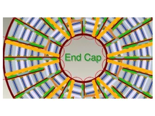
End-cap yoke considerations and halo muon background. Burkhard Schmidt 0 7.12.2010. Muon system Layout. Detector Layout : 3 tail-catcher layers in barrel, 3+1 in EC 2 x3 additional layers interleaved by about 1m of absorber

E N D
End-cap yoke considerationsand halo muon background Burkhard Schmidt 07.12.2010
Muon system Layout • Detector Layout: • 3 tail-catcher layers in barrel, 3+1 in EC • 2 x3 additional layers interleaved by about 1m of absorber • Granularity: about 3cm in both coordinates, matching the HCAL granularity. • Yoke design: • Note summarizes the status of the work as of early summer. • The design shown in the note is obsolete. • Optimization is an iterative process Not present as such in the present design, but will be integrated in the EC
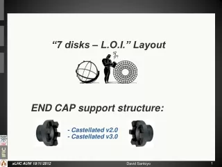
End-cap yoke design Figures show the old design: The present CLIC Muon system design has been discussed with Hubert and a new yoke layout is being worked on. The presence of about 550mm steal blocks without gap is appreciated and simplifies the layout, as most of the stress can be taken by these steal blocks. An effort is made to minimize the dead space (in the old design 6%) and to avoid ‘blind zones’ for (parallel) background muons. In a 2nd step, look more closely at the technology implementation.
Technology Implementation CLIC_ILD side view CLIC_SiD front view Strip length Barrel: ~3m along beam axis 3-4m across octant End-cap: Less intuitive. To be looked at with engineers . But strips not longer than ~3m
Halo Muon Background • Number assumed so far: • Halo muons: ~103 per bunch, 0.8muons/cm2 close to the beamline • too high ! • Latest results of Lawrence Deacon et al.: • Shown at IWLC October 2010: http://ilcagenda.linearcollider.org/getFile.py/access?contribId=259&sessionId=83&resId=0&materialId=slides&confId=4507 • 1.2E4 muons / train at exit of QF1, 10m upstream of IP, and within a 6m radius of the beam line (assuming 10-4 of beam hitting spoilers, based on ideal machine, so should be taken as a minimum value). • “Swapped” layout (Rogelio Tomas) – betatronbefore energy collimation – muon flux is decreased by a factor of 0.4 to 4.8E3 muons/train (presented at IPAC 2010). Modest reduction.
Geometry of cleaning section • 1st attempt: The addition of these muon spoilers results in a factor ~0.1 reduction in muon flux to detector • 2nd attempt: using a simple iterative process does the same with half the length of spoilers. • Trying to optimize further • Distribution files available at: https://www.pp.rhul.ac.uk/twiki/bin/view/JAI/ClicMuon
Halo muon background • Next steps: • Understand results from L. Deacon • Develop an algorithm to identify halo muonsfrom the geometry simulations by L. Deacon