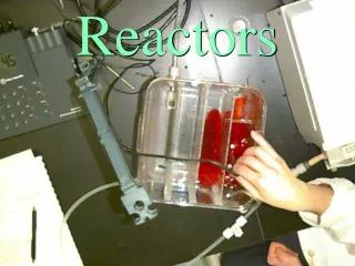
BASIC DESIGN EQUATIONS FOR MULTIPHASE REACTORS
BASIC DESIGN EQUATIONS FOR MULTIPHASE REACTORS. 1. P. A. Ramachandran and R. V. Chaudhari, Three-Phase Catalytic Reactors , Gordon and Breach Publishers, New York, (1983).

BASIC DESIGN EQUATIONS FOR MULTIPHASE REACTORS
E N D
Presentation Transcript
1. P. A. Ramachandran and R. V. Chaudhari, Three-Phase Catalytic Reactors, Gordon and Breach Publishers, New York, (1983). 2. Nigam, K.D.P. and Schumpe, A., “Three-phase sparged reactors”, Topics in chemical engineering, 8, 11-112, 679-739, (1996) 3. Trambouze, P., H. Van Landeghem, J.-P. Wauquier, “Chemical Reactors: Design, Engineering, Operation”, Technip, (2004) Starting Reference
1. Review microkinetic and macrokinetic processes that occur in soluble and solid-catalyzed systems. 2. Review ideal flow patterns for homogeneous systems as a precursor for application to multiphase systems. 3. Derive basic reactor performance equations using ideal flow patterns for the various phases. 4. Introduce non-ideal fluid mixing models. 5. Illustrate concepts through use of case studies. Objectives
Types of Multiphase Reactions Reaction Type Degree of Difficulty • Gas-liquid without catalyst • Gas-liquid with soluble catalyst • Gas-liquid with solid catalyst • Gas-liquid-liquid with soluble or solid catalyst • Gas-liquid-liquid with soluble or solid catalyst (two liquid phases) Straightforward Complex
Hierarchy of Multiphase Reactor Models Model Type Implementation Insight Empirical Ideal Flow Patterns Phenomenological Volume-Averaged Conservation Laws Pointwise Conservation Laws Straightforward Very little Very Difficult or Impossible Significant
Macrokinetic Processes in Slurry Reactors Hydrodynamics of the multi-phase dispersion - Fluid holdups & holdup distribution - Fluid and particle specific interfacial areas - Bubble size & catalyst size distributions Fluid macromixing - PDF’s of the various phases Fluid micromixing - Bubble coalescence & breakage - Catalyst particle agglomeration & attrition Reactor Model Heat transfer phenomena - Liquid evaporation & condensation - Fluid-to-wall, fluid-to-internal coils, etc. Energy dissipation - Power input from variouis sources (e.g., stirrers, fluid-fluid interactions,…)
Macrokinetic Processes in Fixed-Bed Reactors Hydrodynamics of the multi-phase flows - Flow regimes & pressure drop - Fluid holdups & holdup distribution - Fluid-fluid & fluid-particle specific interfacial areas - Fluid distribution Fluid macromixing - PDF’s of the various phases Reactor Model Heat transfer phenomena - Liquid evaporation & condensation - Fluid-to-wall, fluid-to-internal coils, etc. Energy dissipation - Pressure drop (e.g., stirrers, fluid-fluid interactions,…)
Elements of the Reactor Model Macro or Global Analysis Micro or Local Analysis • Gas - liquid mass transfer • Liquid - solid mass transfer • Interparticle and interphase mass transfer • Intraparticle and intraphase diffusion • Intraparticle and intraphase heat transfer • Catalyst particle wetting • Flow patterns for the gas, liquid, and solids • Hydrodynamics of the gas, liquid, and solids • Macro distributions of the gas, liquid and solid • Heat exchange • Other types of transport phenomena
Reactor Design Variables Qout Tout Cout Qin Tin Cin Reactor Product Feed Reactor Process Reaction Flow = f Performance Variables Rates Patterns • Conversion • Flow rates • Kinetics • Macro • Selectivity • Inlet C & T • Transport • Micro • Activity • Heat exchange
Ideal Flow Patterns for Single-Phase Systems Q (m3/s) Q (m3/s) a. Plug-Flow Q (m3/s) Q (m3/s) b. Backmixed Flow
Impulse Tracer Response MTt y(t) x(t) t t Q (m3/s) Reactor System Q (m3/s) Fraction of the outflow with a residence time between t and t + dt E(t) is the P.D.F. of the residence time distribution Tracer mass balance requirement:
Fluid-Phase Mixing: Single Phase, Backmixed Q (m3/s) Mi = Mass of tracer injected (kmol)
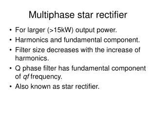
Idealized Mixing Models for Multiphase Reactors Model Gas-Phase Liquid Phase Solid-Phase Reactor Type 1 Plug-flow Plug-flow Fixed Trickle-Bed Flooded-Bed 2 Backmixed Backmixed Backmixed Mechanically agitated 3 Plug-Flow Backmixed Backmixed Bubble column Ebullated - bed Gas-Lift & Loop
Ideal Flow Patterns in Multiphase ReactorsExample: Mechanically Agitated Reactors VR = vG + VL + VC 1 = G + L + C or
First Absolute Moment of theTracer Response for Multiphase Systems For a single mobile phase in contact with p stagnant phases: For p mobile phases in contact with p - 1 mobile phases: is the partition coefficient of the tracer between phase 1 and j
Relating the PDF to Reactor Performance “For any system where the covariance of sojourn times is zero (i.e., when the tracer leaves and re-enters the flowing stream at the same spatial position), the PDF of sojourn times in the reaction environment can be obtained from the exit-age PDF for a non-adsorbing tracer that remains confined to the flowing phase external to other phases present in the system.” For a first-order process: Hp(kc) = pdf for the stagnant phase
Illustrations of Ideal-Mixing Modelsfor Multiphase Reactors Stirred tank Bubble Column Trickle - Bed Flooded - Bed z z G L G L • Plug-flow of gas • Backmixed liquid & catalyst • Batch catalyst • Catalyst is fully wetted • Plug-flow of gas • Plug-flow of liquid • Fixed-bed of catalyst • Catalyst is fully wetted
Intrinsic Reaction Rates Reaction Scheme: A (g) + vB (l) C (l)
Gas Limiting and Plug-Flow of Liquid Key Assumptions 1. Gaseous reactant is limiting 2. First-order reaction wrt dissolved gas 3. Constant gas-phase concentration 4. Plug-flow of liquid 5. Isothermal operation 6. Liquid is nonvolatile 7. Catalyst concentration is constant 8. Finite gas-liquid, liquid-solid, and intraparticle gradients z G L
(Net input by convection) (Input by Gas-Liquid Transport) (Loss by Liquid-solid Transport) - = 0 + Gas Limiting and Plug flow of liquid Constant gas phase concentration valid for pure gas at high flow rate Concentration or Axial Height Relative distance from catalyst particle (1) (2) Dividing by Ar.dz and taking limit dz (3) (4)
Gas Limiting and Plug flow of liquid Solving the Model Equations
Concept of Reactor Efficiency Rate of rxn in the Entire Reactor with Transport Effects Maximum Possible Rate
Gas Limiting and Backmixed Liquid Key Assumptions Stirred Tank Bubble Column 1. Gaseous reactant is limiting 2. First-order reaction wrt dissolved gas 3. Constant gas-phase concentration 4. Liquid and catalyst are backmixed 5. Isothermal operation 6. Liquid is nonvolatile 7. Catalyst concentration is constant 8. Finite gas-liquid, liquid-solid, and intraparticle gradients z G L
Gas Limiting and Backmixed Liquid Concentration or Axial Height Relative distance from catalyst particle • Concentration of dissolved gas in the liquid bulk is constant [≠f(z)] [=Al,0] • Concentration of liquid reactant in the liquid bulk is constant [≠f(z)] [=Bl,0] A in liquid bulk: Analysis is similar to the previous case
(Net input by flow) (Rate of rxn of B at the catalyst surface) = Gas Limiting and Backmixed Liquid A at the catalyst surface: For Reactant B: (Note: No transport to gas since B is non-volatile)
Gas Limiting and Backmixed Liquid Solving the Model Equations
A B Flow Patterns Concepts for Multiphase Systems A - Single phase flow of gas or liquid with exchange between the mobile phase and stagnant phase. Fixed beds, Trickle-beds, packed bubble columns B - Single phase flow of gas or liquid with exchange between a partially backmixed stagnant phase. Semi-batch slurries, fluidized-beds, ebullated beds
C D E Flow Patterns Concepts for Multiphase Systems C, D - Cocurrent or countercurrent two-phase flow with exchange between the phases and stagnant phase. Trickle-beds, packed or empty bubble columns E - Exchange between two flowing phases, one of which has strong internal recirculation. Empty bubble columns and fluidized beds
Axial Dispersion Model (Single Phase) Basis: Plug flow with superimposed “diffusional” transport in the direction of flow @ z = L @ z = 0 Let @ = 1 @ = 0