Introduction to Pneumatics
1.08k likes | 1.64k Vues
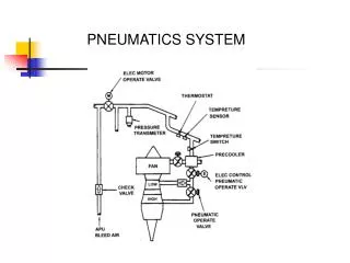
Introduction to Pneumatics. Air Production System. Air Consumption System. What can Pneumatics do?. Operation of system valves for air, water or chemicals Operation of heavy or hot doors Unloading of hoppers in building, steel making, mining and chemical industries

Introduction to Pneumatics
E N D
Presentation Transcript
Air Production System Air Consumption System
What can Pneumatics do? • Operation of system valves for air, water or chemicals • Operation of heavy or hot doors • Unloading of hoppers in building, steel making, mining and chemical industries • Ramming and tamping in concrete and asphalt laying • Lifting and moving in slab molding machines • Crop spraying and operation of other tractor equipment • Spray painting • Holding and moving in wood working and furniture making • Holding in jigs and fixtures in assembly machinery and machine tools • Holding for gluing, heat sealing or welding plastics • Holding for brazing or welding • Forming operations of bending, drawing and flattening • Spot welding machines • Riveting • Operation of guillotine blades • Bottling and filling machines • Wood working machinery drives and feeds • Test rigs • Machine tool, work or tool feeding • Component and material conveyor transfer • Pneumatic robots • Auto gauging • Air separation and vacuum lifting of thin sheets • Dental drills • and so much more… new applications are developed daily
Properties of compressed air • Availability • Storage • Simplicity of design and control • Choice of movement • Economy
Properties of compressed air • Reliability • Resistance to Environment • Environmentally clean. • Safety
What is Air? The weight of a one square inch column of air (from sea level to the outer atmosphere, @ 680 F, & 36% RH) is 14.69 pounds. In a typical cubic foot of air --- there are over 3,000,000 particles of dust, dirt, pollen, and other contaminants. Industrial air may be 3 times (or more) more polluted.
Pressure and Flow Example P1 = 6bar P = 1bar P2 = 5bar Q = 54 l/min (1 Bar = 14.5 psi) P1 P2
Compression ratio = psig + 1 atm One cubic foot of air 1 atm compressor One cubic foot of 100 psig compressed air (at Standard conditions) with 7.8 times the moisture and dirt 7.8 cubic feet of free air CFM vs SCFM Compressed air is always related at Standard conditions. Compressing Air
Compressor 1 ft3 @100 psig -200 F 1 ft3 @100 psig 770 F 1 ft3 @100 psig 770 F 1 ft3 @100 psig 1950 F 100% RH 57.1 grams of H20 0.15% RH .01 grams of H20 100% RH .73 grams of H20 100% RH .01 grams of H20 .72 grams of H20 56.37 grams of H20 Relative Humidity Reservoir Tank Adsorbtion Dryer Compressor Exit Airline Drop
Air Mains Dead-End Main Ring Main
Pressure • It should be noted that the SI unit of pressure is the Pascal (Pa) • 1 Pa = 1 N/m2 (Newton per square meter) • This unit is extremely small and so, to avoid huge numbers in practice, an agreement has been made to use the bar as a unit of 100,000 Pa. • 100,000 Pa = 100 kPa = 1 bar • Atmospheric Pressure • =14.696 psi =1.01325 bar =1.03323 kgf/cm2.
P1 x V1 = P2 x V2 P2 = P1 x V1 V2 V2 = P1 x V1 P2 Example P2 = ? P1 = Pa (1.013bar) V1 = 1m³ V2 = .5m³ P2 = 1.013 x 1 .5 = 2.026 bar Isothermic change (Boyle’s Law)with constant temperature, the pressure of a given mass of gas is inversely proportional to its volume
V1 = T1 V2 T2 V2 = V1 x T2 T1 T2 = T1 x V2 V1 Example V2 = ? V1 = 2m³ T1 = 273°K (0°C) T2 = 303°K (30°C) V2 = 2 x 303 273 = 2.219m³ Isobaric change (Charles Law)…at constant pressure, a given mass of gas increases in volume by 1 of its volume for every degree C in temperature rise. 273 10
P1 x P2 T1 x T2 P2 = P1 x T2 T1 T2 = T1 x P2 P1 Example P2 = ? P1 = 4bar T1 = 273°K (O°C) T2 = 298°K (25°C) P2 = 4 x 298 273 = 4.366bar Isochoric change Law of Gay Lussacat constant volume, the pressure is proportional to the temperature
P1 = ________bar T1 = _______°C ______°K T2 = _______°C ______°K
D = 4 x FE x P Example FE = 1600N P = 6 bar. D = 4 x 1600 3.14 x 600,000 D = 6400 1884000 D = .0583m D = 58.3mm A 63mm bore cylinder would be selected. Force formula transposed
Load Ratio • This ratio expresses the percentage of the required force needed from the maximum available theoretical force at a given pressure. • L.R.= required force x 100% max. available theoretical force • Maximum load ratios • Horizontal….70%~ 1.5:1 • Vertical…….50%~ 2.0:1
Speed control • The speed of a cylinder is define by the extra force behind the piston, above the force opposed by the load • The lower the load ratio, the better the speed control.
Angle of Movement 1. If we totally neglect friction, which cylinder diameter is needed to horizontally push a load with an 825 kg mass with a pressure of 6 bar; speed is not important. 2. Which cylinder diameter is necessary to lift the same mass with the same pressure of 6 bar vertically if the load ratio can not exceed 50%. 3. Same conditions as in #2 except from vertical to an angle of 30°. Assume a friction coefficient of 0.2. 4. What is the force required when the angle is increased to 45°?
Y axes, (vertical lifting force)….. sin x M X axes, (horizontal lifting force)….cos x x M Total force = Y + X = friction coefficients
Example = .01 F = ________ (N) 150kg 40° Force Y = sin x M = .642 x 150 = 96.3 N Force X = cos x x M = .766 x .01 x 150 = 1.149 N Total Force = Y + X = 96.3 N + 1.149 N = 97.449 N
= __ ______kg _____° Force Y = sin x M = Force X = cos x x M = Total Force = Y + X = F = ________ (N)
Example 1 T = 25°C r.h = 65% V = 1m³ From table 3.7 air at 25°C contains 23.76 g/m³ 23.76 g/m³ x .65 r.h = 15.44 g/m³ Relative humidity (r.h.) = actual water content X 100% saturated quantity (dew point) 13
V = 10m³ T1= 15°C T2= 25°C P1 = 1.013bar P2 = 6bar r.h = 65% ? H²0 will condense out From 3.17, 15°C = 13.04 g/m² 13.04 g/m² x 10m³ = 130.4 g 130.4 g x .65 r.h = 84.9 g V2 = 1.013 x 10 = 1.44 m³ 6 + 1.013 From 3.17, 25°C = 23.76 g/m² 23.76 g/m² x 1.44 m³ = 34.2 g 84.9 - 34.2 = 50.6 g 50.6 g of water will condense out Relative Humidity Example 2 13
V = __________m³ T1= __________°C T2= __________°C P1 =__________bar P2 =__________bar r.h =__________% ? __________H²0 will condense out
Formulae, for when more exact values are required • Sonic flow = P1 + 1.013 > 1.896 x (P2 + 1,013) • Pneumatic systemscannot operate under sonic flow conditions • Subsonic flow = P1 + 1.013 < 1.896 x (P2 + 1,013) • The Volume flow Q for subsonic flow equals: • Q (l/min) = 22.2 x S (P2 + 1.013) x P 16
Example P1 = 7bar P2 = 6.3bar S = 12mm² l/min P1 + 1.013 ? 1.896 x (P2 + 1.013) 7 + 1.013 ? 1.896 x (6.3 + 1.013) 8.013 ? 1.896 x 7.313 8.013 < 13.86 subsonic flow. Q = 22.2 x S x (P2 + 1.013) x P Q = 22.2 x 12 x (6.3 + 1.013) x .7 Q = 22.2 x 12 x 7.313 x .7 Q = 22.2 x 12 x 5.119 Q = 22.2 x 12 x 2.26 Q = 602 l/min Sonic / Subsonic flow 16,17
P1 = _________bar P2 = _________bar S = _________mm² Q = ____?_____l/min
Example V = capacity of receiver Q = compressor output l/min Pa = atmospheric pressure P1 = compressor output pressure V = Q x Pa P1 + Pa If Q = 5000 P1 = 9 bar Pa = 1.013 V = 5000 x 1.013 9 + 1.013 V = 5065 10.013 V = 505.84 liters Receiver sizing 22
Example Q = 16800 l/min P1 = 9 bar (900kPa) P = .3 bar (30kPa) L = 125 m pipe length P = kPa/m L l/min x .00001667 = m³/s 30 = .24 kPa/m 125 16800 x .00001667 = 0.28 m³/s chart lines on Nomogram Sizing compressor air mains 31
Example 2 Add fittings to example 1 From table 4.20 2 elbows @ 1.4m = 2.8m 2 90° @ 0.8m = 1.6m 6 Tees @ 0.7m = 4.2m 2 valves @ 0.5m = 1.0m Total = 9.6m 125m + 9.6 = 134.6m =135m 30kPa = 0.22kPa/m 135m Chart lines on Nomogram Sizing compressor air mains 31
Using the ring main example on page 29 size for the following requirements: Q = 20,000 l/min P1 = 10 bar (_________kPa) P = .5 bar (_________kPa) L = 200 m pipe length P = kPa/m L l/min x .00001667 = m³/s
Example • P = 7 bar (700,000 N/m²) • D = 63mm (.063m) • d = 15mm (.015m) • F = x (D² -d²) x P 4 • F = 3.14 x (.063² - .015²) x 700,000 4 • F = 3.14 x (.003969 - .0.000225) x 700,000 4 • F = .785 x .003744 x 700,000 • F = 2057.328 N 54
M = 100kg P = 5bar = 32mm = 0.2 F = /4 x D²x P = 401.9 N From chart 6.16 90KG = 43.9% Lo. To find Lo for 100kg 43.9 x 100 = 48.8 % Lo. 90 Calculate remaining force 401.9 x 48.8(.488) = 196N 100 assume a cylinder efficiency of 95% 196 x 95 = 185.7 N 100 Newtons = kg • m/s² , therefor 185.7 N = 185.7 kg • m/s² divide mass into remaining force m/s² = 185.7 kg • m/s² 100kg = 1.857 m/s² Example
M = _______kg P = _______bar = _______mm = 0.2 F = /4 x D²x P = 401.9 N
Air Flow and ConsumptionAir consumption of a cylinder is defined as:piston area x stroke length x number of single strokes per minute x absolute pressure in bar. Q = D² (m) x x (P + Pa) x stroke(m) x # strokes/min x 1000 4
Example. = 80 stroke = 400mm s/min = 12 x 2 P = 6bar. From table 6.19... 80 at 6 bar = 3.479 (3.5)l/100mm stroke Qt = Q x stroke(mm) x # of extend + retract strokes 100 Qt = 3.5 x 400 x 24 100 Qt = 3.5 x 4 x 24 Qt = 336 l/min.