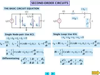
SECOND ORDER CIRCUITS
SECOND ORDER CIRCUITS. Prepared by: Ertuğrul Eriş Reference book: Electric Circuits, Nielsson, Riedel Pearson, Prentence Hall,2007. Update 2: 13August 2012. COURSE ASSESMENT MATRIX. RLC CIRCUITS. Second order circuits Two inductors, two capacitors, one inductor one capacitor


SECOND ORDER CIRCUITS
E N D
Presentation Transcript
SECOND ORDER CIRCUITS Prepared by: Ertuğrul Eriş Reference book: Electric Circuits, Nielsson, Riedel Pearson, Prentence Hall,2007 Update 2: 13August 2012
COURSE ASSESMENT MATRIX Ertuğrul Eriş
RLC CIRCUITS • Second order circuits • Two inductors, two capacitors, one inductor one capacitor • DC Independent source /AC later • Serial or parallel • Second order differential equation • At most second order derivative OR • Two first order differential equations, matrices Ertuğrul Eriş
PARALLEL RLC CIRCUIT ANALYSIS • MATHEMATICAL • Second order single differential equation, or first order two differential equations • Homogenous solution: independent sources deactivated. • Particular solution: independent source type solution • General solution= Homogenous solution + particular solution • CIRCUIT BASED • Natural response • Independent sources are deactivated, initial conditions exsist • Forced solution • Independent sources active (step, basamak); initial conditions are(0) • General solution (Tam, genel çözüm)=Natural response+forced solution Ertuğrul Eriş
SECOND ORDER CIRCUITS Paralel RLC Mathematical Homogenous+particular Circuit based Natural+forced + V0 _ I0 Seri RLC Mathematical Homogenous+particular Circuit based Natural+forced I0 + V0 _ Ertuğrul Eriş
PARALLEL RLC CIRCUIT SECOND ORDER SINGLE EQUATION-1 + V0 _ I0 Second order single differential equation (capacitor voltage, inductor current): Two first order differential equations state equations (Durum Denklemleri ) Would it be enough to solve only one of the above equations? How could we find the other unknowns? Compare left and right hand equations Ertuğrul Eriş
PARALLEL RLC CIRCUIT SECOND ORDER SINGLE EQUATION-2 + V0 _ I0 General (Tam) solution: = Homogenous (Homojen) solution + particular (Özel) solution independent sources deactivated for DC type souces it is a constant, For AC type sources, it is a sinusoidal function How do we know that the sum of homogenous and particular solution is general solution? Linearity!! Difference of homogenous and natural response? Ertuğrul Eriş
PARALLEL RLC CIRCUIT SECOND ORDER SINGLE EQUATION-3 Tam çözüm (General)= = Homojen çözüm (Homogenous) + Özel çözüm (particular) The two unknown parameters in homogenous solution will be calculated by using the two initial conditions on the general solution = Transient state (Geçici hal,rejim) + Steady state (Sürekli hal,rejim) How do we know that the sum of homogenous and particular solution is general solution? Linearity!! Difference of homogenous and natural response? Ertuğrul Eriş
PARALLEL RLC CIRCUIT SECOND ORDER SINGLE EQUATION-4 + V0 _ I0 I(t) independent current source If it is DC source then its derivative is (0) For Vc(t) general solution is equal to homogenous solution while particular solution is (0) A1 and A2 parameters will be calculated by vc(0), iL(0) initial conditions. dvc(0)/dt; diL(0)/dt can be calculated in terms of vc(0), iL(0) Ertuğrul Eriş
PARALLEL RLC CIRCUIT SECOND ORDER SINGLE EQUATION-5 Ertuğrul Eriş
PARALLEL RLC CIRCUIT SECOND ORDER SINGLE EQUATION-6 + V0 _ I0 If current source is a DC source then particular solution is estimated as a constant D and calculated. A1 and A2 parameters will be calculated by the known vc(0), iL(0) initial conditions. dvc(0)/dt; diL(0)/dt will be found by vc(0), iL(0) initial conditions Compare Vc(t) in previous slide and iL(t) (this slide)? Steady state (particular solution) is I, What does this mean? Difference of homogenous and natural response? Ertuğrul Eriş
PARALLEL RLC CIRCUIT SECOND ORDER SINGLE EQUATION-7 Ertuğrul Eriş
CHARACTERISTIC ROOTS For all the three differential equations, chracteristic equations are the same, so the chracteristic roots • Four cases: • Reel roots α2>ω20, Overdamped • Complex conjugate roots α2<ω20, underdamped • Multiple roots α2=ω20, critically damped • Imaginary rootsα=0 Could the charecteristic roots be imaginar in a second order circuit? Why? Ertuğrul Eriş
PARALLEL RLC CIRCUIT STATE EQUATIONS + V0 _ I0 Ertuğrul Eriş
PARALLEL RLC CIRCUIT STATE EQUATION SOLUTION Ertuğrul Eriş
PARALLEL RLC CIRCUIT STATE EQUATION SOLUTION For any chosen K1 and K2 There are infinite number of solutıons. Initial conditions determine the unique solution Ertuğrul Eriş
PARALEL RLC CIRCUIT GENERAL SOLUTION FOR REAL ROOTS-1 VC(0+)=12V, iL(0+)=30 mA C=0,2 μF, L=50 mH, R=200Ω, I=1 A Ertuğrul Eriş
PARALEL RLC CIRCUIT GENERAL SOLUTION FOR REAL ROOTS-2 Ertuğrul Eriş
PARALEL RLC CIRCUIT GENERAL SOLUTION FOR REAL ROOTS «alternative» VC(0+)=12V, iL(0+)=30 mA ,C=0,2 μF, L=50 mH, R=200Ω, I=1 A Ertuğrul Eriş
PARALEL RLC CIRCUIT GENERAL SOLUTION FOR REAL ROOTS + V0 _ I0 VC(0+)=12V, iL(0+)=30 mA C=0,2 μF L=50 mH R=200Ω I=1 A s1 = - 5000r/s, s2 = - 20000r/s iL(t) = -1,277e-5000t + 0,307 e-20000t +1 A, t≥0 Transient and stady state solution, which elements will be short/open circuits, why? Ertuğrul Eriş
PARALEL RLC CIRCUIT GENERAL SOLUTION FOR REAL ROOTS VC(0+)=12V, iL(0+)=30 mA C=0,2 μF L=50 mH R=200Ω I=1 A + V0 _ I0 s1 = - 5000r/s, s2 = - 20000r/s vC(t) = 319e-5000t -307 e-20000t V, t≥0 Transient and stady state solution, which elements will be short/open circuits, why? Ertuğrul Eriş
PARALLEL RLC CIRCUIT STATE EQUATION SOLUTION: COMPLEX ROOTS-1 Eigen vectors are being used! VC(0+)=0V, iL(0+)=-500mA C=0,125μF, L=8 mH, R=20kΩ, Ertuğrul Eriş
PARALLEL RLC CIRCUIT GENERAL SOLUTION: COMPLEX ROOTS-2 Eigen vectors are being used! Ertuğrul Eriş
PARALLEL RLC CIRCUIT GENERAL SOLUTION: COMPLEX ROOTS «ALTERNATIVE» VC(0+)=0V, iL(0+)=-500mA C=0,125μF, L=8 mH, R=20kΩ, Drivitive’s initial conditions are being used! Ertuğrul Eriş
PARALLEL RLC CIRCUIT GENERAL SOLUTION: COMPLEX ROOTS «SHORT CUT» • Vc(t) unknown shortcut solution has been examined in general, • solution for iL(t) is also similar. • Normally k11,K12, K21 and k22 are complex and interim numbers. • While A1 And A2 are real and final required numbers Ertuğrul Eriş
PARALLEL RLC CIRCUIT GENERAL SOLUTION: COMPLEX ROOTS «NUMERICAL EXPAMPLE FOR THE SHORT CUT SOLUTION» VC(0+)=0V, iL(0+)=-500mA C=0,125μF, L=8 mH, R=20kΩ, Ertuğrul Eriş
PARALLEL RLC CIRCUIT GENERAL SOLUTION: COMPLEX ROOTS VC(0+)=0 V, iL(0+)=-500 mA C=0,125 μF L=8mH R=20KΩ I=1 A + V0 _ I0 Transient and stady state solution, which elements will be short/open circuits, why? Ertuğrul Eriş
PARALLEL RLC CIRCUIT GENERAL SOLUTION: COMPLEX ROOTS VC(0+)=0 V, iL(0+)=-500 mA C=0,125 μF L=8mH R=20KΩ I=1 A + V0 _ I0 vC(t) Transient and stady state solution, which elements will be short/open circuits, why? Ertuğrul Eriş
FIRST 500 MICROSECONDS Ertuğrul Eriş
PARALLEL RLC CIRCUIT GENERAL SOLUTION FOR MULTIPLE ROOTS I0 VC(0+)=0V, iL(0+)=-500mA mA C=0,125μF, L=8 H, R=4kΩ, Ertuğrul Eriş
PARALLEL RLC CIRCUIT GENERAL SOLUTION FOR MULTIPLE ROOTS VC(0+)=0V, iL(0+)=-500mA mA C=0,125μF, L=8 H, R=4kΩ, Ertuğrul Eriş
PARALLEL RLC CIRCUIT GENERAL SOLUTION FOR MULTIPLE ROOTS VC(0+)=0V, iL(0+)=-500mA mA C=0,125μF, L=8 H, R=4kΩ, Ertuğrul Eriş
PARALLEL RLC CIRCUIT GENERAL SOLUTION FOR MULTIPLE ROOTS + V0 _ I0 VC(0+)=0 V, iL(0+)=-500 mA C=0,125 μF L=8 H R=4KΩ I=1 A Transient and stady state solution, which elements will be short/open circuits, why? Ertuğrul Eriş
PARALLEL RLC CIRCUIT GENERAL SOLUTION FOR MULTIPLE ROOTS VC(0+)=0 V, iL(0+)=-500 mA C=0,125 μF L=8 H R=4KΩ I=1 A + V0 _ I0 Transient and stady state solution, which elements will be short/open circuits, why? Ertuğrul Eriş
CIRCUIT BASED PARALLEL RLC CIRCUIT ANALYSIS + V0 _ I0 General solution (Tam)= Natural solution (Öz) + Forced solution (Zorlanmış) independent spurces:deactivated, initial conditions iexsist independent sources: active, initial conditions (0) İnitial conditions (0) !! Difference of homogenous and natural response? Ertuğrul Eriş
PARALLEL RLC CIRUITS: NATURAL RESPONSE, REAL ROOTS EXAMPLE + V0 _ I0 VC(0+)=12V, iL(0+)=30 mA Ertuğrul Eriş
PARALLEL RLC CIRUITS: NATURAL RESPONSE, REAL ROOTS EXAMPLE VC(0+)=12V, iL(0+)=30 mA Ertuğrul Eriş
PARALLEL RLC CIRUITS: NATURAL RESPONSE, REAL ROOTS EXAMPLE Ertuğrul Eriş
PARALLEL RLC CIRUITS: NATURAL RESPONSE, REAL ROOTS EXAMPLE VC(0+)=12V, iL(0+)=30 mA vc(t)= (-14e-5000t+26e-20000t) v, t≥0 iL(t)=(56e-5000t-26e-20000t) mA, t≥0 iR(t)=(-70e-5000t+130e-20000t) mA, t≥0 iC(t)= (14e-5000t-104e-20000t) mA, t≥0 Ertuğrul Eriş
PARALLEL RLC CIRUITS: NATURAL RESPONSE, REAL ROOTS EXAMPLE VC(0+)=12 V, iL(0+)=30 mA s1 = - 5000r/s s2 = - 20000r/s iL(t)=(56e-5000t-26e-20000t) mA, t≥0 Ertuğrul Eriş
PARALLEL RLC CIRUITS: NATURAL RESPONSE, REAL ROOTS EXAMPLE VC(0+)=12 V, iL(0+)=30mA s1 = - 5000r/s ; s2 = - 20000r/s vc(t)= (-14e-5000t+26e-20000t) v, t≥0 Ertuğrul Eriş
PARALLEL RLC CIRUITS: NATURAL RESPONSE, COMPLEX ROOTS EXAMPLE 8mH V(0)=0, I(0)=-500mA Short cut method has been applied Ertuğrul Eriş
PARALLEL RLC CIRUITS: NATURAL RESPONSE, COMPLEX ROOTS EXAMPLE 8mH V(0)=0, I(0)=-500mA Ertuğrul Eriş
PARALLEL RLC CIRUITS: NATURAL RESPONSE, COMPLEX ROOTS EXAMPLE 8mH V(0)=0, I(0)=-500mA Ertuğrul Eriş
PARALLEL RLC CIRUITS: NATURAL RESPONSE, MULTIPLE ROOTS VC(0+)=0V, iL(0+)=-500mA C=0,125μF, L=8 H, R=4kΩ, 4kΩ 0,125uF 8H Ertuğrul Eriş
PARALLEL RLC CIRCUIT STATE EQUATION NATURAL RESPONSE: MULTIPLE ROOTS Ertuğrul Eriş
PARALLEL RLC CIRUITS: NATURAL RESPONSE, MULTIPLE ROOTS EXAMPLE 4kΩ V(0)= 0, iL(0)= -500 mA V(0)=0, I(0)=-500mA Ertuğrul Eriş
PARALLEL RLC CIRUITS: NATURAL RESPONSE, MULTIPLE ROOTS EXAMPLE 4kΩ V(0)= 0, iL(0)= -500 mA V(0)=0, I(0)=-500mA Ertuğrul Eriş
PARALLEL RLC CIRUITS: FORCED RESPONSE, REAL ROOTS Initial energy 0 İnitial conditions0 VC(0)=0 IL(0) =0 VC(0+)=0, iL(0+)=0 C=0,2 μF, L=50 mH, R=200Ω, I=1 A Ertuğrul Eriş
PARALLEL RLC CIRUITS: FORCED RESPONSE, REAL ROOTS Ertuğrul Eriş