Second Order Analysis
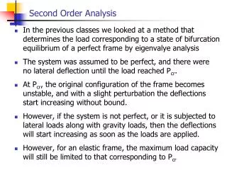
Second Order Analysis . In the previous classes we looked at a method that determines the load corresponding to a state of bifurcation equilibrium of a perfect frame by eigenvalye analysis The system was assumed to be perfect, and there were no lateral deflection until the load reached P cr .

Second Order Analysis
E N D
Presentation Transcript
Second Order Analysis • In the previous classes we looked at a method that determines the load corresponding to a state of bifurcation equilibrium of a perfect frame by eigenvalye analysis • The system was assumed to be perfect, and there were no lateral deflection until the load reached Pcr. • At Pcr, the original configuration of the frame becomes unstable, and with a slight perturbation the deflections start increasing without bound. • However, if the system is not perfect, or it is subjected to lateral loads along with gravity loads, then the deflections will start increasing as soon as the loads are applied. • However, for an elastic frame, the maximum load capacity will still be limited to that corresponding to Pcr
Second Order Analysis • To trace this curve, a complete load-deflection analysis of the frame is necessary. A second order analysis will generate this load-deflection curve • In a second order analysis procedure, secondary effects as the P- and P- effects, can be incorporated directly. As a result, the need for the B1 and B2 factors is eliminated. • In a second-order analysis, the equilibrium equations are formulated with respect to the deformed geometry, which is not known in advance and constantly changing, we need to use an iterative technique to obtain solutions. • In numerical implementation, the incremental load approach is popular. The load is divided into small increments and applied to the structure sequentially.
Second Order Analysis Discretize frame into beam-column elements Form the structure internal force vector Ri1 using all element ri1 For each beam-column element, formulate stiffness matrix k = ko + kg For each element, compute element end forces ri1using TF and P, Ma, Mb Assemble structure stiffness matrix K using k and id array Begin Iteration for i load step For each element, compute P, a, b from e, a, b using element local ke Ri = Ki1Di1 Di1 = [Ki1]-1Ri Where in the i load step, Ri = incremental load vector Ki1 = structure secant stiffness matrix Di1= incremental displacement vector For each element, Compute e, a, b from di1 using Td For each element, Extract di1 from Di1 Di1 = Di + Di1
Second Order Analysis Form the structure internal force vector Ri2 using all element ri2 Form the structure internal force vector Ri1 using all element ri1 For each element, compute element end forces ri2using TF and P, Ma, Mb Form the structure external force vector Ri+1 = Ri + Ri Evaluate unbalanced force vector Qi1 = Ri+1 - Ri1 For each element, compute P, a, b from e, a, b using element local ke Repeat until convergence, where Qij approx. 0 For each element, using the current value of axial force P Update element k For each element, Compute e, a, b from di2 using Td Assemble element k to form updated structure stiffness matrix Ki2 For each element, Extract di2 from Di2 Di2=Di + (Dik) Di2=[Ki2]-1Qi1
Second Order Analysis • After convergence, Di+1 = Din = Di + Dik • Assumed another load increment, and go back to begining
AISC (2005) Specifications Chapter C – Stability Analysis and Design
C1. Stability Design Requirements • 1. General Requirements • Stability shall be provided for the structure as a whole and for each of its elements. • Any method that considers the effects of the following on the stability of structure and elements is permitted: • Influence of second-order effects (P-D and P-d) produced by flexural, shear, and axial deformations • Geometric imperfections • Member stiffness reduction due to residual stress • All component and connection deformations that contribute to lateral displacements must be considered in the analysis • The methods prescribed in this Chapter C and Appendix 7 satisfy these requirements
C1. Stability Design Requirements • 1. General Requirements • For structures designed by elastic analysis, individual member stability and stability of the structure as a whole are provided jointly by: • Calculation of the required load effects (Pr, Vr, Mr) for members and connection using one of the methods specified in C2.2 • Designing members and connections using the specifications of Chapters D, E, F, G, H, and I. e.g., for beam-column members using the interaction equations of Chapter H. • For structures designed by inelastic analysis, the provisions of Appendix 1 must be satisfied.
C2 CALCULATION OF LOAD EFFECTS • C2.2b Design by first order analysis. • First order analysis does not account for the effects of structural deflections (due to applied loads) on the member load effects, i.e., the second order effects. This is covered in CE474 or any matrix structural analysis class. • Required strengths (Pr, Vr, Mr) are permitted to be determined by a first-order analysis with all members designed using K=1.0 provided that: • The required compressive strength (Pr) for all beam-columns satisfy the limitation Pr < 0.5 PY • All load combinations must include an additional lateral load Ni applied in combination with other loads. Ni is applied at each level (or story) of the structure and its value is:
C2 Calculation of Load Effects Ni = 2.1 (DH/L) Yi≥ 0.0042 Yi Where, Yi = design gravity load applied at level i in kips DH/L = maximum ratio of story drift (DH) to height (L) for all stories in the structure. DH = first order inter-story drift due to design loads • This notional load Ni must be considered independently in two orthogonal directions of the structure. • The non-sway amplification of beam-column moment is considered by applying the B1 amplification to the moment calculated from first order analysis.
C2 Calculation of Load Effects • The amplified first-order elastic analysis method defined in Section C2.1b is also an accepted method or second-order elastic analysis of braced, moment, and combined frames. • The required second-order flexural strength Mr and axial strength Pr must be determined as: Mr = B1 Mnt + B2 Mlt Pr = Pnt + B2 Plt • where, B1 = Cm/ (1-Pr/Pe1) ≥ 1.0 … Here, Pr=Pnt+Plt B2 = 1/(1-SPnt/SPe2) ≥ 1.0 • where, Pe1= elastic buckling resistance of member in plane of bending calculated on the basis of no sidesway = p2 EI/(K1L)2 • K1 = effective length factor in plane of bending assuming no sway and set equal to 1.0 unless analysis indicates otherwise
C2 Calculation of Load Effects • Where, SPe2= elastic buckling resistance for the story determined by sidesway buckling analysis • For moment frames, SPe2 can be determined as the column elastic buckling resistances for in-plane sway buckling • K2 = column effective length in plane of bending calculated based on sidesway buckling analysis • For all other types of lateral load resisting systems, it is permitted to use: SPe2 = RmSHL/DH where, Rm =1.0 for braced, and 0.85 for moment frames DH = first-order inter-story drift due to lateral forces H = story shear produced by same lateral forces
C2 Calculation of load effects • Design by second-order analysis • Any second-order elastic analysis method that considers both P-D and P-d effects may be used. • All gravity-only load combinations must include a minimum lateral load applied at each level of the structure of 0.002 Yi, where Yi is the design gravity load applied at level i (kips). • This notional lateral load will be applied independently in both orthogonal directions of the structure. • The notional lateral load limits the error caused by neglecting initial out-of-plumbness and member stiffness reduction due to residual stresses in the analysis.
C2 Calculation of load effects • Design by second-order analysis (cont.) • Calculate the ratio of second-order drift to first-order drift. This ratio can be calculation from analysis or using the equation for B2 (presented later). • If this ratio is less than 1.1 then members are permitted to be designed using effective length K=1.0. • If this ratio is greater than 1.1 but less than 1.5, then the members must be designed using K factor determined from a sidesway buckling analysis of the structure. Stiffness reduction factor due to column inelasticity is permitted in the determination of the K – factor. For braced frames K=1.0 • If this ratio is greater than 1.5, then must use the direct analysis approach given in Appendix 7.
App. 7 Direct Analysis Method • The available strength (capacity) of members can be obtained from the provisions of applicable chapters E, F, G, H, or I. • For beam-columns designed using Chapter H, the nominal column strengths Pn can be determined using K=1.0. • The required strength for members, connections, and other structural elements shall be determined from a second-order elastic analysis. • This second-order analysis must include P-D and P-d effects, and must include all deformation contributions from members and connections. • It is permitted to use any general second-order analysis method or even the B1, B2 factor method provided these factors are based on reduced member stiffness defined later. • Methods of analysis that neglect the P-d (B1) effect are permitted if Pr < 0.15 Pe in the plane of bending.
App. 7 Direct Analysis Method • While conducting the second order analysis, notional loads must be applied to the framing system to account for the effects of geometric imperfections, inelasticity, or both. • Notional lateral loads must be applied at each framing level and specified in terms of the gravity loads at that level. Ni=0.002 Yi • The gravity loads used to determine the notional loads will be associated with the load combination being evaluated. • Notional loads will be applied in the direction that adds to the destabilizing effects under the specified load combination • The notional load coefficient of 0.002 is based on assumed initial out-of-story plumbness=H/500. • As mentioned earlier, if the ratio of second order-to-first order interstory drift is < 1.5, then notional lateral loads can be applied to only the gravity loading combinations. • Additionally, it is permitted to use assumed out-of-plumbness geometry in the analysis instead of the notional load
App. 7 Direct Analysis Method • While conducting the second-order analysis, a reduced flexural stiffness EI* must be used for all the members. EI* = 0.8 t E I where, t = 1.0 , if Pr/PY≤ 0.5 and, t = 4[Pr/PY (1-Pr/PY)] , if Pr/PY>0.5 • You can choose to not use the t factor but then an additional 0.001 Yi load must added to the notional load Ni • A reduced axial stiffness EA* must be used for members whose axial stiffness will contribute to lateral stability.
Checking member strength (Chapter H) • Design of members under flexure and axial force (H1) • For doubly and singly symmetric members in flexure and compression with moments primarily in one plane it is permitted to consider two independent limit states: • In-plane instability • Out-of-plane buckling • For the limit-state of in-plane instability: For Pr/Pc≥0.2 Pr/Pc+8/9[Mrx/Mcx]≤1.0 For Pr/Pc<0.2 Pr/2Pc + [Mrx/Mcy] ≤1.0 Where, Pc = column strength for in-plane buckling Mcx = beam strength for in-plane bending
Checking member strength (Chapter H) • For the limit-state of out-of-plane instability: Pr/Pco + (Mr/Mcx)2≤1.0 where, Pco = column strength for out-of-plane buckling Mcx = beam flexural-torsional buckling strength • If bending occurs only about the weak axis then the moment ratio in the above equation must be neglected because flexural-torsional buckling is not possible. • If biaxial bending occurs with Mr/Mc >0.05 in both axes. For Pr/Pc≥ 0.2 Pr/Pc + 8/9 (Mrx/Mcx+Mry/Mcy) ≤1.0 For Pr/Pc≤ 0.2 Pr/2Pc + Mrx/Mcx+Mry/Mcy ≤1.0 where Pc is column strength according to Ch. E Mc is beam strength according to Ch. F.