Investigating Image Distance and Height Relationship in Concave Mirrors
This experiment explores the relationships between object distance, image distance, object height, and image height in relation to a concave spherical mirror. By systematically adjusting the distance between the mirror and an object and measuring the resulting image formed on a screen, we analyze how changes in distance affect the inverses of image and object distances, as well as the proportionality between object height and image height. This research aids in understanding fundamental optics principles and contributes to error analysis in experimental physics.


Investigating Image Distance and Height Relationship in Concave Mirrors
E N D
Presentation Transcript
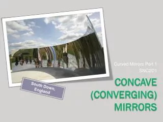
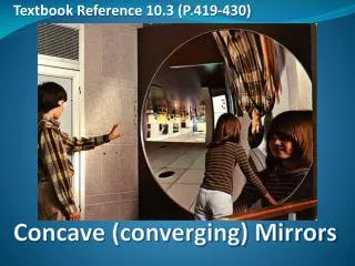
(JL)^2 [aka Jackie and Jocelyn] Converging mirrors
Purpose • Determine the relationship between object distance and image distance for real images in a concave spherical mirror • Determine the relationship between object height and image height for a set object distance
Hypotheses • The inverse of image distance will be linearly related to the inverse of object distance • The object height will be directly proportional to image height
Focal Length • Focal point – where rays parallel to the principal axis come to a focus • Focal length – distance between focal point and center of the mirror
Determining Focal Length • Set curved mirror on track facing an open window. • Set screen on track between window and mirror. • Adjust distance between screen and mirror until focused image (far away object through window, like a power pole) appears on the screen. Measure this distance with meter stick.
Procedure – Part 1 • Place object 15 focal lengths from mirror using cart tracks. • Place the screen between mirror and object/light source (see diagram). • Move the screen until a focused image of the object appears on the screen. • Measure and record the image height that appears on the screen and the distance between the screen and the mirror (image distance). • Decrease object distance by 1 focal length and repeat process until 3 focal lengths away from mirror. • Change distance increments to 5 cm. Continue process until 2 focal lengths away. • Reduce distance increments to 1 cm. Continue process until 1 cm less than 1 focal length away.
Sample Calcs 1/object distance = (1/do) Example: 1/do = 1/390 cm 1/do = 0.003 1/cm 1/image distance = (1/di) Example: 1/di = 25 cm 1/di = 0.040 1/cm
Mathematical Analysis 1/di 1/Image distance 1/do 1/object distance y = mx + b 1/di = k (1/do) + b k = Δ(1/di)/Δ(1/do) k = -1.05 1/cm / 1/cm k = -1.05 b = 0.0419 1/cm 1/di = -1.05 (1/do) + 0.0419 1/cm All slopes and values by LoggerPro
Error analysis: k Accepted Value: 1 Experimental Value (Source: magnitude of 1/di vs. 1/do graph slope): 1.05 ABS error: ǀAccepted value-Experimental valueǀ ǀ 1 – 1.05 ǀ 0.05 Relative error: ABS/accepted value (0.05)/ (1) 0.05 5% error
Error analysis: b Accepted Value: 1/focal length = 1/26 cm = 0.0385 1/cm Experimental Value (Source: y-intercept of 1/di vs. 1/dograph): 0.0419 1/cm ABS error: ǀAccepted value-Experimental valueǀ ǀ 0.0385 1/cm – 0.0419 1/cm ǀ 0.0034 1/cm Relative error: ABS/accepted value (0.0034 1/cm)/ (0.0385 1/cm) 0.0883 8.8% error
Error discussion • The method for taking data for this part largely relied on eyeballing distances and heights, so that was probably the largest source of error. • Also, for distance, we used a ruler to measure distances, which we had to constantly reset—so distances may not have been consistent, esp. with room darkness.
Results 1/di = b- k(1/do) k = 1 b = 1/f 1/di = 1/f - (1/do) 1/di + 1/do = 1/f
Part 2/3 procedure • Place mirror on stand, at head of track. • Use large lamp as light source. Place smallest arrow card in front holder. Move light source 1.5 focal lengths from mirror. • Place screen between light source and mirror. Do not block light source. Adjust mirror so that image appears on screen. • Move screen until image focuses. • Measure image height and object height with ruler. • Repeat process for all arrow cards, recording the height of actual arrow as well. • Move light source until it is 2.5 focal lengths from the mirror and repeat entire process.
Math analyses part 2 hiImage height ho Object height hi∝ ho y = mx hi = k (ho) k = Δhi/ Δho k = 1.89 cm/cm k = 1.89 hi = 1.89 ho All slopes and values by LoggerPro
Error part 2 Accepted Value: f/(do – f) = 26 cm / [1.5 (26cm) – 26 cm] = 2 Experimental Value (Source: magnitude of hivs. hograph slope): 1.89 ABS error: ǀAccepted value-Experimental valueǀ ǀ 2 – 1.89 ǀ 0.11 Relative error: ABS/accepted value 0.11/2 0.055 5.5% error
Error discussion • Same as in part 1: eyeballing distances was the largest source of error, as well as estimating where the image focused exactly.
Results part 2 hi = k(ho) k = f/(do – f) hi = [f/(do – f)](ho)
Math analysis part 3 hi Image height ho Object height hi ∝ ho y = mx hi = k (ho) k = Δhi/ Δho k = 0.593 cm/cm k = 0.593 hi = 0.593 ho All slopes and values by LoggerPro
Error part 3 Accepted Value: f/(do – f) = 26 cm / [2.5 (26cm) – 26 cm] = 0.667 Experimental Value (Source: magnitude of hi vs. ho graph slope): 0.593 ABS error: ǀAccepted value-Experimental valueǀ ǀ 0.667 – 0.593 ǀ 0.074 Relative error: ABS/accepted value 0.074/0.667 0.111 11% error
Error discussion • Same as in parts 1 and 2: eyeballing distances was the largest source of error, as well as estimating where the image focused exactly.
Results part 3 [This might possibly look familiar.] hi = k(ho) k = f/(do – f) hi = [f/(do – f)](ho)
Let’s put it all together! From experiment 1: 1/di + 1/do = 1/f So: 1/di = 1/f- 1/do 1/di = do/fdo- f/fdo 1/di = (do- f)/fdo do/di = (do- f)/f di/do = f/(do- f) From experiments 2 and 3: hi = [f/(do – f)](ho) hi / ho= f/(do – f) hi / ho= di/do