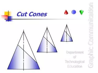
Cut Cones
Cut Cones. Graphic Communication. Department of Technological Education. Cut Cones. At the end of this unit you will be able to:. Identify a Cone and draw orthographic views of Cones with cut surfaces. Project a cut surface on a Cone between the Elevation, Plan and End Elevation.

Cut Cones
E N D
Presentation Transcript
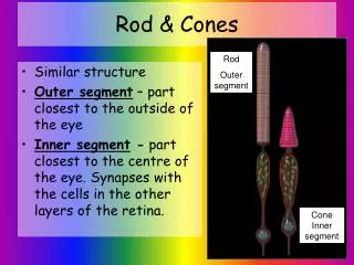
Cut Cones Graphic Communication Department of Technological Education
Cut Cones At the end of this unit you will be able to: • Identify a Cone and draw orthographic views of Cones with cut surfaces. • Project a cut surface on a Cone between the Elevation, Plan and End Elevation. • Construct a Surface Development of a Cone. • Draw the True Shape of a cut surface on a Cone.
Department of Technological Education Cut cone • The given views show the Front Elevation and part Plan of a cut cone. • Draw the following views :- • Complete Plan • End Elevation • Development • True Shape of cut
Department of Technological Education Finding position of End Elevation Start drawing the End Elevation by projecting the height and width from the given views.
Department of Technological Education Drawing Generators on Plan Use 30o and 60o lines to divide the Plan into 12 equal parts. 12 11 1 10 2 Number each of the points on the Plan. 9 3 8 4 7 5 6
Department of Technological Education Transfer Generators from Plan to Elevation Project each of the points from the Plan onto the Elevation base. 12 11 1 10 2 9 3 Number each of the points on the Elevation making sure that the numbers correspond with those on the Plan. 8 4 7 5 6 12 1 2 10 11 9 3 8 7 6 5 4
1 2 1 1 1 1 0 2 9 3 8 4 7 5 6 12 1 2 10 11 9 3 8 7 6 5 4 Department of Technological Education Drawing generator on Elevation Draw generators from the apex of the cone to each of the points found on the base of the cone.
12 11 1 10 2 9 3 8 4 7 5 6 1 0 1 1 1 2 1 2 9 3 8 7 6 5 4 Department of Technological Education Drawing generators onto End Elevation Project the position of the generators onto the End Elevation by projecting the points from the Plan. 1 Number each of the points on the End Elevation. Draw generators from the apex to the base. 7 8 10 11 9 6 12 5 4 3 2 1
12 11 1 10 2 9 3 8 4 7 5 6 7 8 10 11 1 0 1 1 1 2 1 2 9 6 12 9 3 5 4 3 2 1 8 7 6 5 4 Department of Technological Education Finding cut points on End Elevation Project the points where the generators on the Elevation cross the cut onto the End Elevation. Mark each of the points found with a small dot.
7 8 10 11 1 0 1 1 1 2 1 2 9 6 12 9 3 5 4 3 2 1 8 7 6 5 4 Department of Technological Education Completing End Elevation Complete the End Elevation by drawing a smooth curve through each of the point and then darkening the other outlines on the view. 1 2 1 1 1 1 0 2 9 3 8 4 7 5 6
7 8 10 11 1 0 1 1 1 2 1 2 9 6 12 9 3 5 4 3 2 1 8 7 6 5 4 Department of Technological Education Finding cut points on Plan • Project the points from the cut on the Elevation up to the correct generator lines on the Plan. (Note that points 6 and 12 will not be able to be found at this time.) 1 2 1 1 1 1 0 2 9 3 8 4 7 5 6 Mark each of the points found with a small dot
1 0 9 8 1 0 1 1 1 2 9 8 7 6 Department of Technological Education Finding points 6 and 12 on Plan (alternative 1) • Project point 6 and 12 onto the outside generator on the Elevation. 1 2 1 1 1 2 Project this point up to the centre line of the Plan. 3 4 7 5 6 Use compasses to rotate this point onto the correct generators for points 6 and 12. Mark each of these points with a small dot 7 1 2 8 9 1 0 1 1 3 6 1 2 5 5 4 4 3 2 1
1 1 1 0 9 8 4 7 5 6 8 7 6 5 4 4 3 2 1 Department of Technological Education Finding points 6 and 12 on Plan (alternative 2) • Project points 6 and 12 from the End Elevation onto the correct generators on the Plan. 1 2 1 2 3 7 1 0 1 1 1 2 1 2 8 9 1 0 1 1 9 3 6 1 2 5
Department of Technological Education Completing Plan • To complete the Plan draw a smooth curve through each of the 12 points found. 1 2 1 1 1 1 0 2 9 3 8 4 7 5 6 7 1 0 1 1 1 2 1 2 8 9 1 0 1 1 9 3 6 1 2 5 8 7 6 5 4 4 3 2 1
1 2 1 1 1 1 0 2 9 3 8 4 7 5 6 7 1 0 1 1 1 2 1 2 8 9 1 0 1 1 9 3 6 1 2 5 8 7 6 5 4 4 3 2 1 Department of Technological Education Development of surface (1) • Mark the position where the apex of the Development will be placed. 9 Draw the first generator. 10 11 Draw the base line of the Development. 12 Step off the size to each generator point along the base. 1 2 Number each of the points found. 3 4 Draw generator lines from the apex to each of the points on the base. 5 6 7 8 9
1 2 1 1 1 1 0 9 2 1 0 9 3 1 1 8 4 1 2 7 5 6 1 2 3 4 5 6 7 8 7 1 0 1 1 1 2 8 9 1 0 1 1 9 9 6 1 2 5 8 7 6 4 3 2 1 Department of Technological Education Development of surface (2) It is necessary to find the ‘true length’ of the cut points along each generator. To find these sizes project a line through each point on the cut of the Elevation to the outside generator. • Mark each of the found points with a small dot. 1 2 3 5 4
If the development of the outer surface was to be made from sheet metal then it would have been developed starting with the shortest edges to the outside. The reason is that less work and materials would be required for the joins Department of Technological Education Development of surface (3) • Measure the distance from the apex to each point on the outside generator. 1 2 1 1 1 1 0 9 2 Transfer this size to the correct generator on the Development. 1 0 9 3 1 1 8 4 1 2 7 Mark each point with a small dot. 5 6 1 2 Draw a smooth curve through each point found. 3 4 Darken each of the other outlines on the Development. 5 6 7 8 7 1 0 1 1 1 2 1 2 8 9 1 0 1 1 9 9 3 6 1 2 5 8 7 6 5 4 4 3 2 1
1 2 1 1 1 1 0 9 2 1 0 9 3 1 1 8 4 1 2 7 5 6 1 2 3 4 5 6 7 8 7 1 0 1 1 1 2 1 2 8 9 1 0 1 1 9 9 3 6 1 2 5 8 7 6 5 4 4 3 2 1 Department of Technological Education True Shape of cut (1) • Project each of the points on the cut of the Elevation away at right angles to the cut surface. 10 9 11 8 7 12 6 1 5 2 4 3 Draw a datum line on the True Shape – in this case the centre line has been chosen. Number each of the lines projected up to the True Shape.
1 2 1 1 1 1 0 2 9 3 8 4 7 5 6 7 1 0 1 1 1 2 1 2 8 9 1 0 1 1 9 3 6 1 2 5 8 7 6 5 4 4 3 2 1 Department of Technological Education True Shape of cut (2) • Measure the sizes from the cut points to the centre line on the Plan and transfer each of these sizes to the correct lines on the True Shape. • Note – These sizes can also be measured from the End Elevation. • Mark each of the points with a small dot. 10 9 11 8 7 12 6 1 9 5 2 4 1 0 3 1 1 1 2 1 2 3 4 5 6 7 8 9
10 9 11 8 1 2 7 12 1 1 1 6 1 1 0 9 5 2 2 4 1 0 3 9 3 1 1 8 4 1 2 7 5 6 1 2 3 4 5 6 7 8 7 1 0 1 1 1 2 1 2 8 9 1 0 1 1 9 9 3 6 1 2 5 8 7 6 5 4 4 3 2 1 Department of Technological Education True Shape of cut (3) • To finish the True Shape draw a smooth curve through each of the points found. The final drawing should look like this.