Download
1 / 43
450 likes | 498 Vues
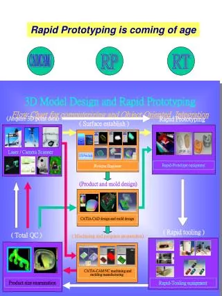
RAPID PROTOTYPING (RP). CAD/CAM/CAE. RAPID PROTOTYPING (RP). Prototyping is one of the step to finalize a product design. A prototype is an original working model of the product, and can be called as the first stage of manufacturing. It helps in conceptualization of a design.

E N D
RAPID PROTOTYPING (RP) CAD/CAM/CAE
RAPID PROTOTYPING (RP) • Prototyping is one of the step to finalize a product design. • A prototype is an original working model of the product, and can be called as the first stage of manufacturing. • It helps in conceptualization of a design. • Before start of production a prototype is usually fabricated and tested. • Manual prototyping by a skilled craftsman has been an age old practice for many centuries.
RAPID PROTOTYPING (RP) • Second phase of prototyping started around mid-1970s,when a soft prototype modeled by 3D curves and surfaces could be • stressed in virtual environment, • simulated and • tested with exact material and other properties. • Third and the latest trend of prototyping, i.e., Rapid Prototyping (RP) is layer-by-layer material deposition.
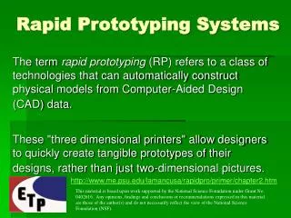
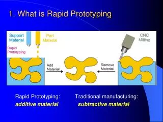
RAPID PROTOTYPING (RP) WHAT IS RP • Rapid Prototyping (RP) is also known as “Toolless Model Making”, “Solid Freeform Fabrication”, “Generative Manufacturing”, “Layered Manufacturing”, “Desk-top manufacturing”, "computer automated manufacturing" etc. • The first technique for rapid prototyping became available in the late 1980s and was used to produce models and prototype parts. • Rapid prototyping is the automatic construction of physical objects using solid free form fabrication at a lower cost. • RP enable components to be made without the need for conventional tooling in the first instance or indeed without the need to engage the services of skilled model-makers.
RAPID PROTOTYPING (RP) DEFINITIONS OF RP • Rapid Prototyping (RP) can be defined as a group of techniques used to quickly fabricate a scale model of a part or assembly using three-dimensional computer aided design (CAD) data.
RAPID PROTOTYPING (RP) MATERIAL • Some techniques use two materials in the course of constructing parts. • The first material is the part material and the second is the support material (to support overhanging features during construction). • The support material is later removed by heat or dissolved away with a solvent or water.
RAPID PROTOTYPING (RP) MATERIAL • In some cases, the RP part can be the final part, but typically the RP material is not strong or accurate enough. • When the RP material is suitable, highly convoluted shapes (including parts nested within parts) can be produced because of the nature of RP.
RAPID PROTOTYPING (RP) USE OF RP
RAPID PROTOTYPING (RP) CATEGORIES OF MANUFACTURING PROCESSES
RAPID PROTOTYPING (RP) SURFACE FINISH • In all commercial RP processes, the part is fabricated by deposition of layers contoured in a (x-y) plane two dimensionally. • The third dimension (z) results from single layers being stacked up on top of each other, but not as a continuous z-coordinate. • Therefore, the prototypes are very exact on the x-y plane but have stair-stepping effect in z-direction. • If model is deposited with very fine layers, • i.e., smaller z-stepping, model looks like original.
RAPID PROTOTYPING (RP) WHY RAPID • Neither RAPID nor PROTOTYPE • Construction of a model with traditional methods take from several hours to several days, depending on the method used and the size and complexity of the model. • RP needs hours ranging from 2 to 72. • RP can typically produce models in a few hours, although it can vary widely depend on the type of machine being used and the size and number of models being produced simultaneously.
RAPID PROTOTYPING (RP) • The reasons of Rapid Prototyping are: • To increase effective communication. • To decrease development time. • To decrease costly mistakes. • To minimize sustaining engineering changes. • To extend product lifetime by adding necessary features • and eliminating redundant features early in the design.
RAPID PROTOTYPING (RP) • Rapid Prototyping decreases development time by allowing corrections to a product to be made early in the process. • By giving engineering, manufacturing, marketing, and purchasing a look at the product early in the design process, mistakes can be corrected and changes can be made while they are still inexpensive. • The trends in manufacturing industries continue to emphasize the following: • Increasing number of variants of products. • Increasing product complexity. • Decreasing delivery time. • Rapid Prototyping improves product development by enabling better communication in a concurrent engineering environment.
RAPID PROTOTYPING (RP) APPLICATIONS • Rapid prototyping has the following applications. • In the field of making patterns and mould and dies for casting and injection mouldings. • In electronic and automotive sector. • In medical industry to develop medical devices and instruments. • In aerospace field for satellites, spacecraft, aircraft, planes, interior of a airplane cockpit etc.
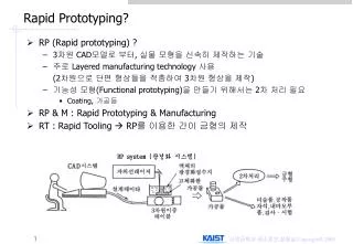
RAPID PROTOTYPING (RP) METHODOLOGY OF RAPID PROTOTYPING • Basic methodology in current RP techniques follows: • A CAD model is first constructed • It is then converted to STL format. The resolution can be set to minimize stair stepping. • RP machine processes .STL file by creating sliced layers of the model. • The first layer of the physical model is created. • The model is then lowered by the thickness of the next layer. • Additional layers are bonded on the top of the first shaped according to their respective cross sectional planes. • This process is repeated until the prototype is complete. • The model and any supports are removed. • The surface of the model is then finished and cleaned.
RAPID PROTOTYPING (RP) RP systems • A survey in 1999 identified some 40 different RP manufacturing approaches. • Some of these are well established “main stream” RP systems while others are more recent arrivals with much to prove. • Also included in the list are systems that are still at the development stage and may not become commercially available, feasible RP systems.
RAPID PROTOTYPING (RP) RP Processes • RP processes can be classified into three types: • Liquid based • The initial material is resin, which solidify under light. • STL (Steriolithography) • Solid based • Material is solid: wire, roll or laminate • FDM (Fused Deposited Modeling) , LOM (Laminated Object Manufacturing) • Powder based • Powder is used as input. • SLS (Selective Laser Sintering)3D Printing
3DP three-dimensional printing 3DWM three-dimensional welding and milling BPM ballistical particle manufacture CAM-LEM computer aided manufacturing-laminated engineering materials CC contour crafting CLOM curved laminated object manufacturing DLF direct light fabrication DLMS direct laser metal sintering ECLD-SFF electrochemical liquid deposition for solid freeform fabrication EDSSM extrusion and deposition of semi-solid metals EFF extrusion freeforming EPDFF electrophotographic powder deposition for freeform fabrication FDC fused deposition of ceramics FDM fused deposition modelling FDMet fused deposition of metals FFF fast freeform fabrication FI fast inkjet GMAW gas metal arc welding LCRHLS local chemical reaction heat by laser scanning LCVD laser chemical vapour deposition LDM laser diode manufacturing
LENS laser engineered net shape LM layered manufacture LML laser microchemical lathe LOM laminated object manufacturing M2SLS multimaterial selective laser sintering Meso SDM mesoscopic shape deposition manufacturing Mold SDM mold shape deposition manufacturing PLD pulsed laser deposition PPD pointwise powder deposition RFP rapid freeze prototyping RBC robocasting RPBPS rapid pattern based powder sintering RSLA refrigerative stereolithography SALD selective area laser deposition SADVI selective area laser deposition and vapour infiltration SGC solid ground curing SLA stereolithography SLPR selective laser powder remelting SLS selective laser sintering TIF temperature induced forming TLP thick layer prototyping WFDM wirefeed direct metals
RAPID PROTOTYPING (RP) RAPID PROTYPING TECHNIQUES • A large number of competing technologies are available in the marketplace. • As all are additive technologies, their main differences are found in the way layers are built to create parts. • Some are melting or softening material to produce the layers where others are laying liquid materials thermosets that are cured with different technologies. • In the case of lamination systems, thin layers are cut to shape and joined together.
STEREOLITHOGRAPHY (SLA) • Stereolithography was the first RP process made commercially available in 1988. • SLA was developed by 3D Systems of Valencia, CA, USA. • The company was founded in 1986, and since then, a number of different RP techniques have become available. • It builds models layer by layer by Ultra Violet laser scanning of a photo reactive resin. • Resin gets cured (polymerized) when impinged by UV laser. • On completion of all layers, the object is placed in a UV curing chamber to ensure complete solidification. • Automotive, aerospace, electronics and medical sector use SLA as rapid & inexpensive method of producing prototypes.
STEREOLITHOGRAPHY (SLA) • A SL machine consists of a build platform, which is mounted in a vat of resin and a UV Helium-Cadmium or Argon ion laser. • The laser scans the first layer and platform is then lowered equal to one slice thickness and left for short time (dip-delay) so that liquid polymer settles to a flat and even surface and prevent bubble formation. • The new slice is then scanned. • Schematic diagram of a typical Stereolithography apparatus is shown in figure. • Once the complete part is deposited, it is removed from the vat and then excess resin is drained. • It may take long time due to high viscosity of liquid resin. • The green part is then post-cured in an UV oven after removing support structures.
STEREOLITHOGRAPHY (SLA) • In this process photosensitive liquid resin which forms a solid polymer when exposed to ultraviolet light is used as a fundamental concept. • Due to the absorption and scattering of beam, the reaction only takes place near the surface and voxels of solid polymeric resin are formed.
STEREOLITHOGRAPHY (SLA) • Blade spreads resin on the part as the blade traverses the vat. • This ensures smoother surface and reduced recoating time. • It also reduces trapped volumes which are sometimes formed due to excessive polymerization at the ends of the slices. • This would otherwise result in an island of liquid resin having thickness more than slice thickness is formed.
STEREOLITHOGRAPHY (SLA) Highlights of Stereolithography • The first Rapid Prototyping technique and still the most widely used. • Inexpensive compared to other techniques. • Uses a light-sensitive liquid polymer. • Requires post-curing since laser is not of high enough power to completely cure. • Parts are quite brittle and have a sticky surface. • Accuracy in z can suffer. • Support structures are typically required. • Process is simple: There are no milling or masking steps required. • Uncured material can be toxic. Ventilation is a must.
STEREOLITHOGRAPHY (SLA) Summary of the SLA process Materials available : Epoxy-based photocurable resins Minimum laser beam : 0.2 mm Layer thickness : 0.05 - 0.25 mm Finishing available : Models can be lightly sanded and sprayed with standard non-water based paints Tooling methods available : Vacuum casting, reaction injection moulding, direct injection mould tooling, metal spray tooling, investment casting
STEREOLITHOGRAPHY (SLA) The sequence of steps for producing an Stereolithography layer is shown:
Its advantages are that • it is well proven technique, • requires no attention • high dimensional accuracy and • best surface finish • Complex geometry, easily obtained • Some of the disadvantages are that • the technique requires support structure, • the components can get warped • the resin is expensive • can be hazardous to the environment. • The initial cost of the process is high and • it requires long time to heat and to cool down. STEREO LITHOGRAPHY (SLA)