Download
1 / 45
490 likes | 1.52k Vues
Treatment of CMP Waste Streams. B.M. Belongia, Y. Sun Dr. J.C. Baygents, Dr. S. Raghavan The University of Arizona Joe O’Sullivan Pall Corp. 1999 Arizona Board of Regents for The University of Arizona. Outline. Background Treatment Strategies

E N D
Treatment of CMP Waste Streams B.M. Belongia, Y. Sun Dr. J.C. Baygents, Dr. S. Raghavan The University of Arizona Joe O’Sullivan Pall Corp. 1999 Arizona Board of Regents for The University of Arizona
Outline • Background • Treatment Strategies • Electrocoagulation/Electrodecantation Studies • pH Effects & Electrode Compartments • Solid/Liquid Separation • Copper Removal • Cross-flow filtration • MicrozaTM UF Systems • Summary
Significance • Large quantities of waste slurry generated from CMP • ~ 6 L of waste slurry generated per wafer • 0.1 - 0.5 % solids and ~ 40 ppm copper ions • Efficient disposal or recycle strategies need to be developed to comply with environmental regulations. • Recycling would require that the dilute waste slurry be concentrated to the initial slurry solids content and the particle size remain unchanged.
Slurry Types • Oxide slurry • Silica is the abrasive material • Suspension is stabilized with either NH4OH or KOH; pH = 10 - 11 • Used to polish oxide layers • Particle size: 50-100 nm
Slurry Types (cont’d) • Metal • Abrasive is primarily aluminum oxide, but some contain silica • Contains an oxidizer, either ferric nitirate, potassium iodate or hydrogen peroxide • pH = 3 - 5 • Used to polish tungsten and copper (recently popular) interconnects • Particle size: 100 - 300 nm
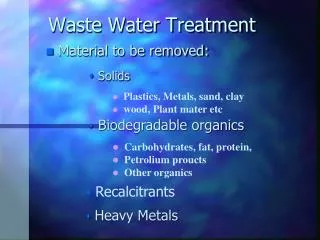
Why Treat CMP Wastewater? • Suspended solids too high to discharge to sewer • Traditional flocculation and clarification requires large tanks and lots of chemical addition • A need to reclaim water at the individual facility
NEW SLURRY 6–10wt% solids WATER TO POLISHING LOOP RINSE WATER SLURRY POLISHING TOOL WATER USED SLURRY MIRACULOUS PROCESS! 0.02–0.5wt% solids 2 –40ppm Cu SOLIDS WASTE SOLIDS
Treatment Objective • To develop a generic methodology for the treatment of CMP waste streams. e.g. a copper CMP waste may contain: • 0.02 – 0.5% solids • 2 – 40ppm copper ions • An organic complexant (e.g. EDTA, Citric Acid) • A corrosion inhibitor (e.g. BTA)
Treatment Strategies • 1. Electrocoagulation/Electrodecantation (EC/ED) • University of Arizona research • Possible follow on to ultrafiltration • 2. Cross-flow filtration • Pall MicrozaTM ultrafiltration system
EC/ED • Electrocoagulation • used to treat waste steams; electric field applied for a short period, suspension allowed to settle in absence of field — rate of settling was found to be enhanced • Electrodecantation • used to concentration proteins, viruses, natural rubber latex, and various inorganic sols
Cathode (-) (Stainless Steel) Sample Port Suspension Membrane Anode (+) (Stainless Steel) Water EC/ED Apparatus
Electrode Reactions Membrane (-) Electrode 2H+ + 2e- H2 (+) Electrode 2H20 4H+ + 4e- + O2 or 2H2O + 2e- H2 + 2OH- Suspension pH increases Water pH decreases
3.5V/cm pH Cathode Chamber Anode Chamber Time (min) pH Changes Electrophoretic Mobility of Al2O3 cm2/V·s 10-4 1mM KNO3 pH
Membrane Liquid Level Clarified Liquid (Sample Zone) c/c0 Cathode Anode Solids 1.75V/cm 3.50V/cm 7.00V/cm 14.00V/cm Time (min) EC/ED of Al2O3 Initial Cond. 1300 mS/cm Initial pH 6.0
cCu/c0Cu Time (min) Copper Removal during EC/ED Initial Cond. 1300 mS/cm Initial pH 6.0 1.75V/cm 3.50V/cm 7.00V/cm 14.00V/cm
Copper Distribution Initial Suspension 220ml @ 34ppm Cu Membrane 165 ml 4.2ppm Cu (9.7%) 97 ml 16.0ppm Cu (20.5%) Cathode Plated Cu (16.3%) Anode 44ml 68.0ppm Cu (39.4%)
EDTA EDTA Cu2+ Cu2+ Al2O3 Al2O3 Effect of EDTA and Cu on Al2O3 Particle Charge pH 6 + - + - - + - + - - + - + + Electrophoretic Mobility cm2/V·s 10-4 + + Al2O3 Al2O3 + 184ppm EDTA Al2O3 + 40ppm Cu + 184ppm EDTA pH
Cu2+ (EDTA)2- [(EDTA)Cu]- Cu(OH)2 OH OH OH OH OH OH Anode OH OH OH OH OH OH Cathode Copper Distribution Membrane pH 6
Membrane Clarified Liquid 0.5% solids Cathode Anode Solids 29% EC/ED of Concentrated Al2O3 Wastes c0 12% solids c/c0 Initial pH 6.0 Initial Cond. 1300 mS/cm Time (min) 3.50V/cm
Highly Concentrated Suspension Recirculated Suspension Water Cross-flow filtration Electrocoagulation Apparatus Waste Permeate Solids Filtration and EC/ED in Tandem Pall Corp. patented technology to treat CMP waste.
Summary of EC/ED Method • Alumina suspension can be dewatered by EC/ED. • Copper can be simultaneously removed from the clarified layer. • plating out onto the cathode • in situ precipitation? • pH changes are critical to the success of the EC/ED process.
Cost and Power Consumption (Using $0.05/kWhr) For 7.0V/cm, 90mins Cost: $0.014/l $0.08/wafer @ 6 l/wafer For 3.5V/cm, 90mins Cost: $0.002/l $0.01/wafer @ 6 l/wafer 1.75V/cm 3.50V/cm 7.00V/cm Work (kW·hr/l) 10-3 Time (min)
Feed Retentate Membrane Solute A Solute B Permeate What is Ultrafiltration?
10 MICROFILTERS 1 1 10 0.1 100 0.01 1000 0.001 0.0001 Micron (µm) Factors Affecting Separations SIZE DIFFUSIVITY IONIC CHARGE DENSITY
Cross Section of MicrozaTM Hollow Fiber Membrane Uniform outer surface skin further improves mechanical properties, facilitates design and provides extra assurance of removal efficiency Macroporous regions allow low pressure differential and enhanced flow rate. Uniform skinned membrane with narrow pore range for highly efficient separation characteristics. Dense porous layer provides exceptional mechanical strength and fiber reliability.
MicrozaTM UF Systems • Process dilute CMP wastewater • 0.02% to 0.1% total suspended solids • Treat oxide, metal or mixture of waste • Concentrate all suspended solids • up to 15-17% • Permeate is free of suspended solids • can pretreat to remove ferric ion and soluble silica • can use as RO makeup water
Challenges of Treating CMP Wastewater • Abrasive material • expect 18-24 months service life on UF modules • Broad pH range • oxide, metal or mixed waste • polyacrylonitrile membrane, pH 2-10 • Prevention of membrane fouling • high linear velocity • reverse filtration
Portable MicrozaTM CMP Test System with Single 0.1 m2 UF Module
Chemical Treatment for Removal of Soluble Silica • Formation of silicate • Precipitation of magnesium/iron silicate • iron silicates pH 8-9 • magnesium silicates pH 10.5-11
Silica Solubility vs. pH 1000 900 , 800 700 600 500 Silica Solubility (mg/L) 400 , 300 200 , , , , , , , 100 0 0 0 2 4 6 8 10 12 pH
Chemical Treatment for Removal of Soluble Silica (cont’d) • Holding tank upstream of UF system • Typical reaction time of 30 minutes - + SiO + 2KOH SiO (silicate) + 2K 2 3 NaOH + MgCl Mg (OH) 2 Mg (OH) + H SiO MgSiO (s) + 2H O 2 2 3 3 2 Magnesium Silicate
Chemical Treatment for the Removal of Ferric Ion • Form hydroxy complexes in acidic media • yellow-orange in color • Neutralization results in hydrous ferric oxide • reddish-brown precipitate
Chemical Treatment for the Removal of Ferric Ion (cont’d) • Caustic injection upstream of UF system • Instantaneous reaction 2+ - 2 Fe (H O) (OH) + 4 OH Fe O . 13 H O 2 5 2 3 2 hydrous ferric oxide yellow-orange in color reddish-brown precipitate
Copper CMP Waste • Abrasive is primarily aluminum oxide • Contains an oxidizer, typically hydrogen peroxide • pH = 3 • Used to polish copper interconnects • particle size: 100-300 nm
Treatment of Copper CMP Waste • Soluble copper • Assuming 5000 wafer starts per week with five levels of copper results in 6 kg of copper per week • Classified as both metal finishing waste and semiconductor waste
Removal of Soluble Copper • Precipitation of Cu(OH)2 by Addition of Caustic • Removal of Copper by I/E • Conventional treatment method in Printed Circuit Board Industry and Plating Industry • Achievable Effluent Levels of < 0.1 ppm of copper • 10K Gallons of Water per cubic foot of resin at a influent level of 10 ppm copper • Electrowinning of copper
Turn-key System for Treatment of Copper CMP Waste • Removal of suspended solids by UF • Removal of Soluble copper by I/E and possibly electrowinning • Further treatment required to generate RO-ready water
Schematic of a Water Reclamation System from CMP Waste Slurry CMP WASTE SLURRIES from POLISHERS RECLAIMED WATER RECLAIMED WATER REVERSE OSMOSIS and/or ION EXCHANGE PERMEATE MICROZA UF System BUFFER TANK TO WASTE TREATMENT REJECT CONCENTRATION FILTRATE FILTER PRESS CONCENTRATE PRE-TREATMENT
Dewatering of UF Concentrate • UF Concentrate • Maximum of 17% Total Suspended Solids • Dewatering Via a Filter Press for Landfill Disposal • Treat with Fluoride Waste • Treat Separately • RCRA Paint Filter Test • Non-Hazardous Material • pH Adjustment • Addition of coagulant • Addition of flocculant
Flux vs. Concentration Factor (X) 90 45.0 80 40.0 Flux X (2ndY) 70 35.0 60 30.0 50 25.0 Flux, lmh Conc Factor 40 20.0 30 15.0 20 10.0 10 5.0 0 0.0 0 1 2 3 4 5 6 7 Time, hr Flux Profile for UF SystemTypical for Mixed CMP Slurry Waste
Buffered Tank ManagementSized for 20 m3/hr of Mixed CMP Waste
WASTE SLURRY FEED FROM CMP TOOLS PERMEATE RF PERMEATE UF RINSE FORWARD PREFILTER PROCESS PERMEATE TRANSFER F-1 BUFFER FEED TANK RETENTATE UF RACK UF RACK No.1 No.2 FEED/BATCH REVERSE TANK FILTRATION TANK RECIRCULATION FEED TRANSFER RF/PERMEATE PUMP PUMP PUMP PUMP DRAIN CONCENTRATE DRAIN PUMP Typical MicrozaTM CMP Waste Slurry Concentrating Installation (Single UF Module Skid)
MicrozaTM CMP Waste Slurry Installation (Multiple UF Module Skids)
Percent Initial Conc VCF Flowrate (GPM) # of Modules Recovery 0.1 % 10X 90 20 5 0.1% 50X 98 20 6 0.2% 10X 90 20 5 0.1% 10X 90 50 13 0.1% 50X 98 50 16 Microza UF System SizingOxide CMP Waste
Microza UF System SizingMixed Oxide and Mixed Metal CMP Waste # of Modules Percent Initial Conc VCF Flowrate (GPM) Recovery 0.1 % 10X 90 20 7 0.1% 50X 98 20 8 0.1% 10X 90 50 18 0.1% 50X 98 50 21