Download
1 / 53
530 likes | 679 Vues
Project X: Status, Strategy, Meeting Goals. Steve Holmes SLAC Seminar May 19, 2011. Outline. Strategic Context Project X Reference Design R&D Plan Status and Timeline Collaboration Status Project X website: http://projectx.fnal.gov. Fermilab Long Range Plan.

E N D
Project X: Status, Strategy, Meeting Goals Steve HolmesSLAC SeminarMay 19, 2011
Outline • Strategic Context • Project X Reference Design • R&D Plan • Status and Timeline • Collaboration Status Project X website: http://projectx.fnal.gov SLAC Seminar - S. Holmes
FermilabLong Range Plan Fermilab is the sole remaining U.S. laboratory providing facilities in support of accelerator-based Elementary Particle Physics. Fermilab is fully aligned with the strategy for U.S. EPP developed by HEPAP/P5. • The Fermilab strategy is to mount a world-leading program at the intensity frontier, while using this program as a bridge to an energy frontier facility beyond LHC in the longer term. Project X is the key element of this strategy SLAC Seminar - S. Holmes
Mission Elements • A neutrino beam for long baseline neutrino oscillation experiments • 2 MW proton source at 60-120 GeV • High intensity, low energy protons for kaon, muon, and neutrino based precision experiments • Operations simultaneous with the neutrino program • A path toward a muon source for possible future Neutrino Factory and/or a Muon Collider • Requires ~4 MW at ~5-15 GeV • Possible missions beyond EPP • Standard Model Tests with nuclei and energy applications SLAC Seminar - S. Holmes
Concept Evolution • Three Project X configurations have been developed, in response to limitations identified at each step: • Initial Configuration-1 (IC-1) • 8 GeV pulsed linac + Recycler/MI • Fully capable of supporting neutrino mission • Limited capabilities for rare processes • Initial Configuration-2 (IC-2) • 2 GeV CW linac + 2-8 GeV RCS + Recycler/MI • Fully capable of supporting neutrino mission • 2 GeV too low for rare processes (Kaons) • Ineffective platform for Neutrino Factory or Muon Collider • Reference Design • 3 GeV CW linac + 3-8 pulsed linac + Recycler/MI • Ameliorates above deficiencies SLAC Seminar - S. Holmes
Reference Design SLAC Seminar - S. Holmes
Reference Design Capabilities • 3 GeV CW superconducting H- linac with 1 mA average beam current. • Flexible provision for variable beam structures to multiple users • CW at time scales >1 msec, 10% DF at <1 msec • Supports rare processes programs at 3 GeV • Provision for 1 GeV extraction for nuclear energy program • 3-8 GeV pulsed linac capable of delivering 300 kW at 8 GeV • Supports the neutrino program • Establishes a path toward a muon based facility • Upgrades to the Recycler and Main Injector to provide ≥ 2 MW to the neutrino production target at 60-120 GeV. • Utilization of a CW linac creates a facility that is unique in the world, with performance that cannot be matched in a synchrotron-based facility. SLAC Seminar - S. Holmes
Functional Requirements SLAC Seminar - S. Holmes
Functional Requirements SLAC Seminar - S. Holmes
Beam Configurations3 GeV Operating Scenario 1 msec period at 3 GeV Muon pulses (16e7) 81.25 MHz, 100 nsec @ 1MHz 700 kW Kaon pulses (16e7) 20.3 MHz 1540 kW Nuclear pulses (16e7) 10.15 MHz 770 kW Ion source and RFQ operate at 4.2 mA 75% of bunches are chopped @ 2.5 MeV maintain 1 mA over 1 msec Separation scheme Transverse rf splitter SLAC Seminar - S. Holmes
Pulsed Linac • The Reference Design utilizes a superconducting pulsed linac for acceleration from 3 to 8 GeV • ILC style cavities and cryomodules • 1.3 GHZ, b=1.0 • 28 cryomodules (@ 25 MV/m) • ILC style rf system • 5 MW klystron • Up to four cryomodules per rf source • Must deliver 26 mA-msec to the Recycler every 0.75 sec. Options: • 1 mA x 4.4 msec pulses at 10 Hz • Six pulses required to load Recycler/Main Injector • 1 mA x 26 msec pulses at 10 Hz • One pulse required to load Main Injector SLAC Seminar - S. Holmes
Performance Goals Linac Particle Type H- Beam Kinetic Energy 3.0 GeV Average Beam Current 1 mA Linac pulse rate CW Beam Power 3000kW Beam Power to 3 GeV program 2870 kW Pulsed Linac Particle Type H- Beam Kinetic Energy 8.0 GeV Pulse rate10Hz Pulse Width 4.3 msec Cycles to MI 6 Particles per cycle to MI 2.61013 Beam Power to 8 GeV340 kW Main Injector/Recycler Beam Kinetic Energy (maximum) 120 GeV Cycle time 1.4 sec Particles per cycle 1.61014 Beam Power at 120 GeV 2200 kW simultaneous SLAC Seminar - S. Holmes
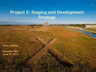
Siting SLAC Seminar - S. Holmes
R&D Program • The primary elements of the R&D program include: • Development of a wide-band chopper • Capable of removing bunches in arbitrary patterns at a 162.5 MHz bunch rate • Development of an H- injection system • Require between 4.4 – 26 msec injection period, depending on pulsed linac operating scenario • Superconducting rf development • Includes six different cavity types at three different frequencies • Emphasis is on Q0, rather than high gradient • Typically 2E10, 15 MV/m (CW) • 1.0E10, 25 MV/m (pulsed) • Includes appropriate rf sources • Includes development of partners • Goal is to complete R&D phase by 2015 SLAC Seminar - S. Holmes
R&D ProgramWideband Chopper • Approach • Four wideband kickers place at 180o in the 2.5 MeV MEBT • Helical or meander-stripline travelling wave deflectors • Wideband amplifier • Requirements • 1 nsec rise/fall time • 1 nsec flat top pulse duration • 50-200 Ω load impedance • >500 V pulse amplitude • >60 MHz average repetition rate • Performance (simulation) • 0.16% beam loss with kicker off • 100% beam removal with kicker on SLAC Seminar - S. Holmes
R&D ProgramWideband Chopper SLAC Seminar - S. Holmes
R&D Program H- Injection • RDR Configuration • Inject and accumulate into the Recycler with single turn transfer to MI • Injection charge 26 mA-ms (1 mA × 4.4 ms – 6 injections and 10 Hz) • Optional configuration of interest • Inject 1 mA directly into the Main Injector in a single pulse over 26 ms, bypassing the Recycler • Reduced complexity • Reduced linac energy, from 8 to 6 GeV • Default technology Carbon Foil Charge Exchange (stationary foil) • Low beam current/long injections time creates many “parasitic” interactions, and dominate the foil issues: • Foil heating, beam loss, emittance growth. (c.f. 1 mA 2300 turns) • Number of parasitic hits determined by injection insertion design, number of injection turns, linac and ring emittance, painting algorithm, foil size and orientation. • Issues appear manageable up to about 4.3 msec (400 turns). SLAC Seminar - S. Holmes
R&D Program H- Injection Estimates by T. Gorlov, SNS • Injection Stripping technologies (2300 turns) • Unique foil implementation designs-> moving, rotating, segmented • Laser Assisted Stripping (3 Step process) • Laser Power Estimates • Implementation Options • Direct illumination (advances in cryogenic laser amplifiers) • Build up cavity (low power laser but requires cavity in high radiation area) • Use higher wavelength (i.e. 2 mm) to reduce laser power by factor of 4 or 5 SLAC Seminar - S. Holmes
SRF LinacTechnology Map Pulsed CW 650 MHz 0.16-3 GeV b=0.11 b=0.22 b=0.4 b=0.61 b=0.9 b=1.0 325 MHz 2.5-160 MeV 1.3 GHz 3-8 GeV SLAC Seminar - S. Holmes
3 GeV CW LinacBeam Dynamics at 1 mA • 1 s beam envelopes • Transverse (upper) • Longitudinal (lower) SLAC Seminar - S. Holmes
3 GeV CW LinacEnergy Gain per Cavity b=0.9 b=0.61 • Based on 5-cell 650 MHz cavity • Crossover point ~450 - 500 MeV SLAC Seminar - S. Holmes
3 GeV CW LinacCryogenic Losses per Cavity ~42 kW cryogenic power at 4.5 K equivalent SLAC Seminar - S. Holmes
SRF DevelopmentIntegrated ILC/ Project X Plan SLAC Seminar - S. Holmes
SRF DevelopmentCavity/ CM Status • 1300 MHz • 88 nine-cell cavities ordered • ~ 44 received (16 from U.S. industry, AES) • ~ 30 processed and tested, 8 dressed • 1 CM built (DESY kit) + second under construction (U.S. procured) • CM1 is now cold and rf testing is underway • 650 MHz • MOU signed with Jlab for 2 single cell b =0.6 cavities • Order for six b = 0.9 single cell cavities in industry • 325 MHz • 2 SSR1 b =0.22 cavities (Roark, Zannon) both VTS tested • 1 SSR1 dressed and under test at STF • 2 SSR1 being fabricated in India • 10 SSR1 ordered from Industry (Roark) • Design work started on 325 and 650 MHz CM SLAC Seminar - S. Holmes
3 GeV CW LinacChoice of Cavity Parameters • Identify maximum achievable surface (magnetic field) on basis of observed Q-slope “knee” • Select cavity shape to maximize gradient (subject to physical constraints) • Establish Q goal based on realistic extrapolation from current performance • Goal: <25 W/cavity • Optimize within (G, Q, T) space (Initial) Performance Goals Freq (MHz) Bpk(mT) G (MV/m) Q @T (K) 325 60 15 1.4E10 2 650 72 16 1.7E10 2 SLAC Seminar - S. Holmes
SRF Development325 MHz • SSR1 (b=0.22) cavity under development • Two prototypes assembled and tested • Both meet Project X specification at 2 K • Preliminary designs for SSR0 and SSR2 SLAC Seminar - S. Holmes
SRF Development1300 MHz PX (CW) ILC Courtesy of R Geng SLAC Seminar - S. Holmes
Fermilab SRF infrastructure 1st Dressed Cavity Cavity tuning machine VTS HTS VTS String Assembly MP9 Clean Room SLAC Seminar - S. Holmes Final Assembly 1st U.S. built ILC/PX Cryomodule
Cavity processing at Argonne Ultrasonic Cleaning • Joint facility built by ANL/FNAL collaboration • EP processing of 9-cells has started • Together with Jlab, ANL/FNAL facility represents the best cavity processing facilities in the US for ILC or Project X Electropolishing High-pressure rinse SLAC Seminar - S. Holmes
IB4 Tumbling Machine Multi-step process for elliptical cavities using multiple sets of media Current results represent an intermediate step towards a more complete process MUCH less infrastructure required Complete descriptions in prep for publication, presentation at TTC, SRF 2011 SLAC Seminar - S. Holmes
Test Facilities • New Muon Lab (NML) facility under construction for ILC RF unit test • Three CM’s driven from a single rf source • 9 mA x 1 msec beam pulse • Large extension and supporting infrastructure under construction • Refrigerator to support full duty factor operations • Horizontal test stands for all frequencies • Building extension for additional CM’s and beam diagnostic area • The Meson Detector Building (MDB) Test Facility ultimately comprises: • 2.5 – 10 MeV beam (p, H-): 1% duty factor, 3 msec pulse • 325 MHz superconducting spoke cavity beam tests • Chopper tests • H- beam instrumentation development • Shielded enclosures and RF power systems for testing individual, jacketed 1.3 GHz, 650 MHz, and 325 MHz superconducting RF cavities SLAC Seminar - S. Holmes
NML Facility Layout Capture Cavity 1 (CC1) Future 3.9/Crab Cavity Test Beamlines Cryomodules CC2 RF Gun 5MW RF System for Gun CC1 & CC2 RF Systems 5MW RF System for Cryomodules Future 10MW RF System SLAC Seminar - S. Holmes 32
ILCTA_NML Facility SLAC Seminar - S. Holmes
FNAL Cryomodules Cryomodule 1 built from DESY kit, Installed in NML 3.9 GHz Cryomodule Designed/built at FNAL for DESY Installed and Operating in FLASH Cryomodule 2: cold mass parts from Europe in hand, accumulating the required 8 HTS tested cavities SLAC Seminar - S. Holmes
Expansion of NML Facility New Cryoplant & CM Test Facility (300 W Cryogenic Plant, Cryomodule Test Stands, 10 MW RF Test Area) Funded by ARRA New Underground Tunnel Expansion (Space for 6 Cryomodules (2 RF Units), AARD Test Beam Lines) Existing NML Building SLAC Seminar - S. Holmes
Future NML Complex SLAC Seminar - S. Holmes
MDB Test Facility Layout 325 MHz Spoke Cavity Test Facility 1.3 GHz HTS HTS-2 650 CW RF 1300 CW RF 325 CAGE Scale: Square blocks are 3ft x 3ft Source of cryogenics Ion Source and RFQ MDB Linac enclosure for 10 MEV SLAC Seminar - S. Holmes
MDB Test Facility325 MHz RFQ SLAC Seminar - S. Holmes
MDB Test FacilitySix-Cavity Test • Demonstrate use of high power RF vector modulators to control multiple RF cavities driven by a single high power klystron • Summer 2011 SLAC Seminar - S. Holmes
MDB Long Term PlanChopper and 4-Cavity CM 18° spectrometer ~2.7 m length Actual absorber/shielding 10 m MEBT/CHOPPER 13.4 m Existing ion source and RFQ 0 m 10.5 m 16.9 m 14.2 m 10.5 foot ceiling 0.5 m end 0.5 m end 2.4 m cryostat With cryomodule need additional 3+ meters cave length pending spectrometer line optics design SLAC Seminar - S. Holmes
CD-0 Strategy/Status • Requirements • Mission Needs Statement – approved by Director/Office of Science • Includes a cost range and funding profile • Independent Cost Review – new requirement • CD-1 Plan • Mission Validation Independent Review • DOE sponsored Intensity Frontier Physics Workshop: fall 2011 • Staging • Serious discussion of a staged approach. Building blocks: • LBNE @ 2 MW (60-120 GeV) • Rare process program @ 3 MW (3 GeV) • Short baseline neutrinos (3-8 GeV) • Motivated by desirability to reduce costs of initial steps • Reference Design: ~$1.8B • CW Linac: ~$1.2B • “Day-one” experimental program ~$0.2B SLAC Seminar - S. Holmes
Collaboration Status • Collaboration MOU for R&D phase: ANL ORNL/SNS BNL MSU Cornell TJNAF Fermilab SLAC LBNL ILC/ART • MOU/Addendum on development of High Intensity Proton Accelerators in place between Fermilab and Indian institutes: BARC/Mumbai RRCAT/Indore IUAC/Delhi VECC/Kolkota • Currently working on defining strawman assignments for the construction phase • Reflects in R&D assignments • Draft Collaboration Governance Plan • Discussion in Collaboration Council Meeting SLAC Seminar - S. Holmes
Summary • Project X is central to the U.S. strategy for accelerator based particle physics over the coming decades • World leading programs in neutrinos and rare processes; • Aligned with Muon Accelerators technology development; • Potential applications beyond elementary particle physics • Reference Design established as preferred concept • 5 MW beam power available • 3MW at 3 GeV for rare processes • 2 MW at 60-120 GeV for long baseline neutrinos • CW linac is unique for this application, and offers capabilities that would be hard/impossible to duplicate in a synchrotron • Configuration stable for more than a year • R&D program underway with very significant investment in srf infrastructure and development • DOE sponsored Physics Workshop this fall • Planning based on construction over the period FY16-20 SLAC Seminar - S. Holmes
Backup Slides SLAC Seminar - S. Holmes
Configuration Evolution Physics Requirements SLAC Seminar - S. Holmes
Phase-1 Layout of NML Capture Cavity 2 (CC2) Cryomodule-1 (CM1) (Type III+) 5 MW RF System for CM1 CC2 RF System SLAC Seminar - S. Holmes 50