Download
1 / 50
500 likes | 657 Vues
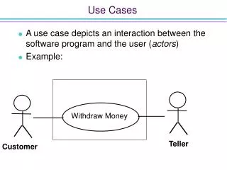
Systems Analysis II Use Cases. INFO 355 Glenn Booker. Use Cases. As part of the activity to define functional requirements, we can capture those requirements in “use cases” “A use case is an activity the system performs, usually in response to a request by the user” (text, 69).

E N D
Systems Analysis IIUse Cases INFO 355 Glenn Booker Week #2
Use Cases • As part of the activity to define functional requirements, we can capture those requirements in “use cases” • “A use case is an activity the system performs, usually in response to a request by the user” (text, 69) Week #2
Use Cases and OO • Though use cases are often associated with object oriented analysis, use cases are not object oriented • They could be used to help capture functional requirements for any type of system Week #2
Finding use cases • Two methods (at least) for finding use cases for a system • User goal technique • Event decomposition technique • To validate a draft list of use cases, the CRUD technique can be used Week #2
User goal technique • The main idea behind this technique is to identify the types of users of a system, then determine what goals or assigned tasks each type of user has when using the system • Those goals often correspond to use cases Week #2
User goal technique • The user goal technique is: • Identify all potential users for a system • (Optional) Classify users by functional role (shipping, marketing, sales) and operational level (operational, management, executive) • Interview each user and determine what goals they have when using the system Week #2
User goal technique • Make a preliminary list of use cases for each type of user • Look for duplicates and inconsistencies across users • Identify when multiple users need the same use case • Review completed list with users and other stakeholders for validation Week #2
Event Decomposition • This approach looks for all events that would lead to the information system being used • Each event typically leads to a use case • Simplify events to ones that have a clearly defined start and end, and achieve a clear business purpose • Those are Elementary Business Processes (EBPs) = use cases Week #2
Event Decomposition • Focusing on events keeps attention on the macro scale purpose of the system, not internal details • Events can be • External – caused by an actor • Temporal – done at fixed time intervals • State – triggered by an internal condition, e.g. low inventory Week #2
Event Decomposition • Focus on events that directly cause the system to be used • Not prior conditions that are invisible to the system • Many important business processes do not involve the system directly! • Avoid trivial use cases (logging on) but DO include system controls (admin functions such as backup) The last point differs from the text! Week #2
Event Decomposition • The event decomposition process is • Identify relevant external events • For each, name a use case • Identify relevant temporal events • For each, name a use case and define when it occurs • Identify relevant state events • For each, name a use case • Omit trivial use cases, but keep system controls Week #2
CRUD technique • Use this technique for verifying an existing list of use cases • Recall CRUD – create, read, update, or delete data • The goal of this technique is to verify at least one use case has been identified to perform all relevant aspects of CRUD • Relevant aspects? Week #2
CRUD technique steps • Identify major data entities for your system • For each, verify that at least one use case does each of CRUD, as appropriate to your system • Add use cases if needed • Make sure data ownership is clear if more than one application interacts Week #2
Naming use cases • Give use cases a short name (2-4 words), starting with an action verb • Track shipment • Create new user • Produce monthly sales report • The reason for brevity is so we can put them on a use case diagram Week #2
Use Case Diagram • A use case diagram summarizes all the major use cases for a system • To define a use case diagram, need: • List of Use Cases • Actors • External Systems (if any) • System Boundary (automation boundary) Week #2
Actors • Actors are types of users of the system – the role of someone who uses the system • Actors must interact directly with the system • Interaction could be through any mechanism – keyboard, mouse, touch screen, card reader, voice, biometric,… Week #2
Actors • Examples of actors include • Customer/Client/Patient/Patron/Donor/Subscriber (if they interact directly) • Manager (should be more specific) • System Administrator • Clerk • Foreman Week #2
External Systems • External systems are any non-human (generally computerized) actor which your system needs to perform one or more use cases • Can be a Timer, to initiate automatically repeating use cases • Are systems you don’t control, and are outside the scope of your system development Week #2
External Systems • Could include systems owned by vendors • E.g. a service to maintain your online catalog • Could be a custom legacy system which isn’t being replaced • E.g. an existing human resource system, or accounting system Week #2
System Boundary • The use case diagram includes a box to show the boundaries of your system • Actors are not within the boundary • External systems are not within the boundary • Box is labeled with your system’s name (not just “System”) • The use case diagram acts like a context diagram Week #2
Naming Use Cases • Each use case should have a brief name, typically 2-4 words • Start with a verb, and end with a noun • Cancel Customer Order • Place Order • Validate New Customer • Number use cases sequentially Week #2
Use Case Diagram Notation • Actors are represented by stick people, with their role below them • Use cases are represented by ovals • External systems are represented by rectangles, with “<<actor>>” before the system name • “<<actor>>” is a stereotype • The “<< >>” should be guillemets Week #2
Sample Use Case Diagram Tip: Straight lines are easier to use! Week #2
Use Case Diagram Notation • Lines connect actors to the use cases they can perform • Hence a major purpose of the use case diagram is to show what functions the system can perform, and who can use them • Notice there is no indication of when use cases are performed, or any of the logic behind them Week #2
Generalization • A common concept for the use case diagram is when one actor has some special use cases, but also can do everything some other actors can • A manager or supervisor can do everything their staff can do, plus additional functions • Show this using generalization Week #2
Generalization • Notice the triangle at the top of the line between Manager and Staff • This means that Manager inherits all use cases which Staff can do • (Also can use generalization in Class diagrams) • Helps keep use case diagram simpler and easier to read Week #2
“Included” Use Cases • When documenting use cases, might find a clear set of activities that appears in two or more use cases • Can pull those activities out and make that an included use case • In Visio, lines to an included use case have the stereotype “<<uses>>” • In other applications, stereotype is “<<includes>>” Week #2
“Included” Use Cases • The included use case is documented separately from the use cases which use it Use case numbering and system boundary omitted Week #2
Subsystem use case diagram • Ideally all actors and use cases should fit on one diagram • If not, it’s ok to have a separate use case diagram for each major subsystem • Specify whether the diagram includes all users (preferred) or a limited subset of them Week #2
Documenting Use Cases • Use cases can be documented to varying levels of detail • We’ll define two of them • Casual use case documentation • Detailed use case documentation • These are local terms for the level of documentation, not Cockburn’s • (that’s pronounced CO-burn) • The text uses ‘Brief’ and ‘Fully developed’ Week #2
Casual Use Case Documentation • Consists of: • Use case number and name • Objective – A sentence to elaborate on the main purpose of the use case • Primary Actor – what actor initiates the use case • Main Success Scenario – a step-by-step description of the events which should occur during this use case Week #2
Detailed Use Case Documentation • Consists of: • Use case number and name • Objective • Primary Actor • Secondary Actor(s) – other actors who play a significant role in this use case • Trigger – what event forces the start of this use case? • Main Success Scenario (MSS) Week #2
Detailed Use Case Documentation • Extensions – when performing the MSS, what other events could occur? • Extensions often include alternate methods of processing, different ways to do the same thing, and error conditions • Performance time – how long it should typically take to perform this use case • Frequency – how often will this use case be performed? • Open Issues – for scope issues, if any Week #2
Beyond Detailed • The MSS and/or extensions should cite included use cases, where appropriate • Additional documentation is possible beyond the detailed template just given – see Cockburn’s site Week #2
Main Success Scenario • The Main Success Scenario describes the interaction between actors and the system in order to perform a use case • They are critical to write well, since later documentation depends upon them (e.g. sequence diagrams) • See Summary of UML Diagrams handout for details on MSS writing Week #2
Main Success Scenario • Where to begin? • For most use cases, you can assume the actor has logged into the system (if needed) and are starting at the application’s Main Menu or its equivalent • A MSS describes a use case in more detail than you would typically consider necessary Week #2
Main Success Scenario • The MSS describes the most common way a use case will be performed successfully • If there are multiple processing options, pick the most frequent one for the MSS, and describe the rest in the Extensions • In the MSS, assume all actions will be successful; describe how to handle unsuccessful outcomes in the Extensions • The MSS is the Disney version of the use case • Extensions are the Tim Burton version Week #2
Main Success Scenario • Typical actor activities in a MSS are: • Navigate through the interface to a defined objective • “Shipping clerk navigates to the New Shipment Screen.” • Notice we didn’t say HOW they navigate, just that it’s accomplished somehow • Enter data onto an interface • “Shipping clerk enters the data for a new shipment.” • Notice every field entered is not specified Week #2
Main Success Scenario • Describe when an actor selects something on an interface • “Dispatch manager selects the number of drivers needed.” • Indicate when an actor completes an activity, such as by submitting data • “Shipping clerk submits the new shipment data.” • This prompts the system to do something with the data Week #2
Main Success Scenario • The only remaining type of actor action is to exit the application, which often isn’t part of a MSS (assume you can always cancel or exit from the system) • So there are few types of things an actor might do during a MSS • System actions can be much more complex Week #2
Main Success Scenario • Typical system actions include: • Create a new interface screen • “System displays Define Shipment screen.” • Change or update the contents of an existing screen • “System updates the screen to show the list of artifacts.” Week #2
Main Success Scenario • Communicate with an external system • “System gets current stock price from NYSE.” • “System emails drivers with shipment info.” • Perform an included use case • “System performs Validate Credit Card use case.” • Perform background processing • “System validates new customer data.” • “System computes the sales tax.” Week #2
Main Success Scenario • Notice that the MSS includes steps which aren’t visible to the actors! • Other background processing might include • “System prioritizes the list of drivers.” • “System produces weekly sales summary.” • Background processing can include any activity needed to prepare data for presenting the results to the actor Week #2
Main Success Scenario • Finally, make sure a MSS achieves the overall objective of the use case! • “System saves new customer data.” • “System updates order status.” • “System deletes completed orders.” • These steps are typically performing one of the CRUD functions Week #2
Main Success Scenario • Writing a MSS might involve making assumptions about where or how data is stored • Can assume there is a place that stores Customer Data, or Shipment Data, etc. • External systems should be labeled consistently throughout the design • Can name interfaces (New Customer Screen), but don’t design them (‘click on the submit button’ = no!) Week #2
Main Success Scenario • Throughout a MSS, look for actions which need to be repeated • Specify in generic terms how many times steps need to be repeated • For each book to be checked out, … • For each driver assigned to a shipment, • Repeat five times, or until login is successful Week #2
Extensions • Extensions, or alternate scenarios, handle when something doesn’t go normally during a use case • Extensions are numbered, starting with the MSS step from which they depart • If an extension starts from step 5, the first extension is a condition called 5.a • Then the steps to respond to that condition are 5.a.1, 5.a.2, etc. • A second extension from step 5 is condition 5.b and has steps 5.b.1, 5.b.2, 5.b.3, etc. Week #2
Extensions Handle • So the lettered step (5.a) describes the condition under which you perform that extension • And the steps under it (5.a.1, 5.a.2, …) are the actor and system actions that follow • Optional processing steps can be an extension; the rest of the MSS isn’t affected if they aren’t used • Adding sales tax to an order • Adding gift wrapping to an order Week #2
Extensions Handle • Failure conditions – when a MSS step can’t be performed successfully • If a search yields no results • If payment is insufficient • Can’t connect to an external system • Alternate processing – when a MSS step can be processed differently • Handle domestic versus international orders • Handle different forms of payment Week #2
Extensions • Assume that interfaces and data transactions inside your system are successful, and won’t result in an extension, e.g. • Saving or reading data locally • Creating or updating interfaces • Otherwise every system step could be an extension! Week #2