Download
1 / 23
230 likes | 350 Vues
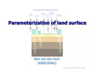
The Development of the HWRF Land Surface Component. Yihua Wu, Ken Mitchell, Mike Ek, Vijay Tallapragada and Robert Tuleya. EMC 9/19/2008. Also Special Thanks To Dingchen Hou Yulong Xia George Gayno Young Kwon. Background. Objective of HWRF GFDL Slab LSM Noah LSM.

E N D
The Development of the HWRF Land Surface Component Yihua Wu, Ken Mitchell, Mike Ek, Vijay Tallapragada and Robert Tuleya EMC 9/19/2008
Also Special Thanks To Dingchen Hou Yulong Xia George Gayno Young Kwon
Background Objective of HWRF GFDL Slab LSM Noah LSM Experimental Design Results and Summary Track and Intensity Runoff Streamflow Future Work Outline Advance LSM Options of LSM, Surface Layer and PBL Linking with EMC's Streamflow Routing Scheme
Background (1) One of the goals of the HWRF model is to serve as input to hydrology and inundation models to forecast hurricane related inland flooding through its land surface component. LGM
Background (2) The GFDL Slab LSM 1. The default LSM in HWRF 2. One soil layer 3. Uses the initial soil moisture from GFS, and the soil moisture field remains fixed in time during the HWRF forecast. 4. Does not predict the runoff response to HWRF precipitation forecasts, thus cannot predict streamflow from HWRF forecasts.
Background (3) The Noah LSM 1) The operational LSM in NCEP's operational mesoscale forecast model (Ek et al., 2003) 2) Multiple soil layers (usually 4 layers: 0-10,10-40, 40-100 and 100-200 cm depth) with a one-layer vegetation canopy 3) Spatially varying root depth and seasonal cycle of vegetation cover 4) Frozen soil physics for cold regions, and improved soil and snowpack thermal conductivity. 5) Predicts soil moisture, soil temperature, land surface skin temperature, land surface evaporation and sensible heat flux, and total runoff. 6) The HWRF-Noah runoff prediction can then be used as forcing input to EMC's Streamflow Routing Scheme (Lohmann et al., 2004). 7) The HWRF-Noah forecasts of soil moisture and runoff are good spatial indicators of soil moisture saturation (water logging) and flooding.
ExperimentalDesign *In conjunction with the new Noah LSM option in HWRF, we felt that the MYJ PBL scheme and MYJ surface layer scheme might work better with the Noah LSM over land.
Study Cases RITA KATRINA DENNIS All runs for Katrina started at 00z Aug 28, 2005
HWRF Predicted Intensities of Katrina Max Wind Speed MSLP MSLP
Hurricane Rain Swaths (inch) Modeled Rainfall N883 N893 Observed Rainfall N686 N696
12 Hour Accum. Rainfall (mm) OBS NAM HWRF 48h 48h 48h 72h 72h 72h Observed rainfall is the rain gauge measurement. Observed rainfall spreads in larger area
4 Layer Soil Moisture at Initial Time 00Z AUG 28, 2005 Soil moisture for NLDAS and NAM are driven by observed precipitation. Initial soil moisture for HWRF is from GFS soil moisture, which is driven by GDAS predicted precipitation, plus nudging to a monthly soil moisture climatology.
Forecasted Soil Moisture for Layer 1 NLDAS NAM HWRF 48h 48h 48h 72h 72h 72h Higher soil moisture along Katrina Path in all of the models. Higher soil moisture in HWRF than in NLDAS and NAM.
Forecasted Soil Moisture for Layer 2 NLDAS NAM HWRF 48h 48h 48h 72h 72h 72h Soil moisture for layer 2 is very similar to the results for layer 1.
12 Hour Surface Runoff (mm) NLDAS NAM HWRF 48h 48h 48h 72h 72h 72h Before Katrina landfall, NLDAS had more surface runoff. After Katrina landfall, HWRF had more surface runoff.
12 Hour Subsurface Runoff (mm) NLDAS NAM HWRF 48h 48h 48h 72h 72h 72h HWRF had more subsurface runoff before and after Katrina landfall, primarily because HWRF initial soil moisture from GFS is too high.
12 Hour Total Runoff (mm) NLDAS NAM HWRF 48h 48h 48h 72h 72h 72h HWRF had more total runoff which is the sum of the surface runoff and subsurface runoff.
Forecasted Stream Flow (m3 s-1) NLDAS NAM HWRF 48h 48h 48h 72h 72h 72h Stream flow is higher in HWRF than in NLDAS and NAM, especially in Southeast of the domain
Stream flow At 30.63N and 89.90W Purple—USGS Measured Daily Values
Summary • The addition of the capability in HWRF to execute the Noah Land Surface Model (Noah LSM) in place of the default GFDL Slab Land Surface Model (Slab LSM). • More combinations of PBL, Surface layer and LSM physics over land. • LSM has small effects on the track and intensity of simulated hurricanes • Linking HWRF-Noah runoff output with EMC's Stream flow Routing Scheme. • The goal is to serve as input to hydrology and inundation models to forecast hurricane related inland flooding
Future Works • To initialize HWRF with realistic initial conditions of soil moisture from NAM and NLDAS, rather than GFS. • To run more hurricane cases to test both HWRF and the stream flow routing scheme. • To explore use of inland flooding models (e.g. from NWS Office of Hydrology or USGS)