VLSI Digital Systems Design
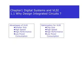
Circuit and Physical Design of Fully-Complementary CMOS Logic Gates. VLSI Digital Systems Design. Fan-in. Fan-in = number of inputs to a gate Examples: Nand g1 (outg1, in1, in2, in3, in4); fan-in = 4 Nor g2 (outg2, in1, in2); fan-in = 2. Fan-out.


VLSI Digital Systems Design
E N D
Presentation Transcript
Circuit and Physical Design ofFully-Complementary CMOS Logic Gates VLSI Digital Systems Design cmpe222_05full_compl_ppt.ppt
Fan-in • Fan-in = number of inputs to a gate • Examples: • Nand g1 (outg1, in1, in2, in3, in4); fan-in = 4 • Nor g2 (outg2, in1, in2); fan-in = 2 cmpe222_05full_compl_ppt.ppt
Fan-out • Fan-out = number of inputs that a gate's output drives • In units of minimum-sized inverters • Examples: • Nand g1 (outg1, a, b, c, d); • Nor g2 (outg2, a, e); • Not g3 (a, f); fan-out = 2 cmpe222_05full_compl_ppt.ppt
Large Fan-in Slows Gate • Resistance of series transistors in pull-up network or pull-down network additive • Two transistors in series will double the rise or fall time compared to single transistor cmpe222_05full_compl_ppt.ppt
Worst-case delay time • Tdf = worst-case fall delay time • Tdf = tinternal-f + k ∙ toutput-f • Tdr = worst-case rise delay time • Tdr = tinternal-r + k ∙ toutput-r • where k = fan-out • in units of minimum-sized inverters cmpe222_05full_compl_ppt.ppt
Gate Delays • Delay tinternal-f toutput-f tinternal-r toutput-r • Units ns ns/pF ns ns/pF • Gate ____ _ _____ _____ _____ • INV 0.08 1.70 0.08 2.10 • ND2 0.20 3.10 0.15 2.10 • ND4 0.68 5.70 0.25 2.10 • ND8 2.44 9.99 0.38 2.20 • NR2 0.14 1.75 0.25 4.10 cmpe222_05full_compl_ppt.ppt
Not 1 pF Nand 8-input And, Case 1 • Nand stage1 (s1out, a, b, c, d, e, f, g, h); • Not stage2 (s2out, s1out); a b c s1out s2out d e f g h 2.44 2.18 cmpe222_05full_compl_ppt.ppt
Nand Nor 1 pF Nand 8-input And, Case 2 • Still 2 stages • Less fan-in a b c d e f g h 0.68 4.35 cmpe222_05full_compl_ppt.ppt
Nand Nor Nand Nand Not 1 pF Nand Nor Nand 8-input And, Case 3 • Twice as many stages • Minimal fan-in a b c d e f g h 0.20 0.25 0.20 2.18 cmpe222_05full_compl_ppt.ppt
8-input And, Comparison • | Stage Stage Stage Stage| 1 2 3 4 TotalCase fall rise fall rise Delay • 1 2.44 2.18 0.00 0.00 4.62 • 2 0.68 4.35 0.00 0.00 5.03 • 3 0.20 0.25 0.20 2.18 2.83 cmpe222_05full_compl_ppt.ppt
Transistor Sizing • Start with minimum-sized devices • Determine critical paths • Increase the gate size along critical paths cmpe222_05full_compl_ppt.ppt
Timing Rules of Thumb, Page 1 • Use Nands • Avoid Nors • Output rise and fall time depend oninput rise and fall times • Keep edges sharp throughout each critical path cmpe222_05full_compl_ppt.ppt
Timing Rules of Thumb, Page 2 • Keep fan-out low • Below 5-10 • Use minimal-sized gates to minimize the load on gates with high fan-out • Drive high fan-out nets with inverters • Keep fan-in low • Unless low power or low area is more important cmpe222_05full_compl_ppt.ppt
aa = poly (input) bb = poly (input) cc = poly (internal) mm = metal (internal) dd = Vdd (metal) ss = Vss (metal) nn = n-diffusion pp = p-diffusion -- = gate ** = contact Layout Layer Key cmpe222_05full_compl_ppt.ppt
Vertical-Transistor Inverter Layout **dddddddddd-Vdd dd ** pp aaaaaa aa pp aa ** aa mm A-aaaa mmmmmm-Z aa mm aa ** aa nn aaaaaa nn ** ss **ssssssssss-Vss cmpe222_05full_compl_ppt.ppt
Horizontal-Transistor Inverter Layout **dddddddddddd-Vdd dd **pp--pp** aa mm A-aaaaaaaa mmmm-Z aa mm **nn--nn** ss **ssssssssssss-Vss cmpe222_05full_compl_ppt.ppt
Horizontal-Transistor Inv Layout w Central Metal Pass-Through **dddddddddddddddd-Vdd dd dd dd **pp--pp**mm** aa cc mmmmmmmmaammmmmmccmmmm aa cc A-aaaaaaaa cccc-Z aa cc mmmmmmmmaammmmmmccmmmm aa cc **nn--nn**mm** ss ss ss **ssssssssssssssss-Vss cmpe222_05full_compl_ppt.ppt
Horizontal-Transistor Inv Layout w Top & Bottom Metal Pass-Thru **dd**dddddddddddd-Vdd pp mmmmmmmmmmmmmmmmmmmmmm pp pppp--pp**mm aa cc aa cc aa cc A-aaaaaaaa cccccc-Z aa cc aa cc aa cc nnnn--nn**cc nn mmmmmmmmmmmmmmmmmmmmmm nn **ss**ssssssssssss-Vss cmpe222_05full_compl_ppt.ppt
Large-Transistor Inverter Layout **dddddddddddd-Vdd dd ddpp--pp **pp--pp** pp--ppmm aa mm A-aaaaaaaa mmmm-Z aa mm nn--nnmm **nn--nn** ssnn--nn ss **ssssssssssss-Vss cmpe222_05full_compl_ppt.ppt
Back-to-Back-TransistorInverter Layout **dddddddddddddddddddddd-Vdd dd dd **pp--pp**pp--pp** aa mm aa A-aaaaaaaa mmmmmmmmmmmmmm-Z aa mm aa aaaammaaaa aa mm aa **nn--nn**nn--nn** ss ss **ssssssssssssssssssssss-Vss cmpe222_05full_compl_ppt.ppt
Advantages of Back-to-Back-Transistor Inverter Layout • Drain area does not increase in size much • Drain capacitance does not increase much • Transistor gain doubled cmpe222_05full_compl_ppt.ppt
**dddddddddddddddddddd-Vdd dd pppppp**pppppp pp----------pp pp--pppppp--pp pp--pp**mm--mmmmmm pp--pppppp--pp mm pp----------pp mm pppppp--pppppp mm aa mm A-aaaaaaaaaa mmmm-Z aa mm nnnnnn--nnnnnn mm nn----------nn mm nn--nnnnnn--nn mm nn--nn**mm--mmmmmm nn--nnnnnn--nn nn----------nn nnnnnn**nnnnnn ss **ssssssssssssssssssss-Vss cmpe222_05full_compl_ppt.ppt
Advantages of Doughnut-Transistor Inverter Layout • Drain area does not increase in size much • Drain capacitance does not increase much • Transistor gain almost quadrupled • Also called “round transistor” connection cmpe222_05full_compl_ppt.ppt
“Line of Diffusion” Layout • Single row of p-transistors abovesingle row of n-transistors • Aligned at common gate connections • Transistors form line of diffusionintersected by polysilicon gate connections • All complementary gatescan be designed this way • Most simple gatescan be designed without a break in the diffusion cmpe222_05full_compl_ppt.ppt
Complex Gate Layout • Convert circuit to two graphs • p-transistor pull-up network • n-transistor pull-down network • Each graphs is the dual of the other • Vertices = source-drain connections • Edges = transistors that connect vertices • Labeled with gate signal name for that transistor cmpe222_05full_compl_ppt.ppt
Euler Path • If two edges are adjacent in one of the graphs • They share a common source-drain connection • They can be connected by abutment • If there is an Euler path • if there is a sequence of edges • containing all edges in the p-graph and the n-graph • that have identical labeling • then the gate can be designed with no breaks cmpe222_05full_compl_ppt.ppt
“Line of Diffusion”Layout Algorithm • Find all Euler paths that cover the n-graphand the p-graph • Find an Euler path for the n-graphand an Euler path for the p-graphthat have identical labeling • labeling = ordering of the gate labels on each vertex • If not found, break the gate in the minimum number of places to achieve step 2by separate Euler paths cmpe222_05full_compl_ppt.ppt
Stacked Transistor Layout • Input signal applied togates of multiple transistors • Transistors stacked on appropriate gate signal • Used for cascaded gates • Xnor • Variation in distance between power linesmakes standard cell layout more difficult • C.f. “line of diffusion” layout cmpe222_05full_compl_ppt.ppt
Nand Nand Or Xnor Logic a z = a Xnor b b cmpe222_05full_compl_ppt.ppt
Nand portion of “Line of Diffusion” Xnor Layout dddddddddddddddddddddddddddddddddddddddddddddd-Vdd dd dd **pp--pp**pp--pp** -- "Line of Diffusion" -- aa mm bb aa mm bb aa mm bb aa mmmmbbmmmmmm- A Nand B aa bb mm **nn--nnnnnn--nn** -- "Line of Diffusion" -- ss aa bb ss aa bb ss aa bb ssssaassssssbbssssssssssssssssssssssssssssssss-Vss aa bb aa bb aa bb A-aa B-bb cmpe222_05full_compl_ppt.ppt
“Line of Diffusion” Xnor Layout dddddddddddddddddddddddddddddddddddddddddddddd-Vdd dd dd dd **pp--pp**pp--pp** **pp--pp**pp--pppppp--pp** aa mm bb mm cc aa bb mm aa mm bb mmmmccmmmmmmaammmmmmbbmmmmmm-Z aa mm bb cc aa mm bb aa mmmmbbmmmmmm**cccc aa mm bb aa bb mm cc aa mm bb **nn--nnnnnn--nn** **nn--nn**nn--nn**nn--nn** ss aa bb ss mm aa bb mm ss aa bb ss mmmmaammmmmmbbmmmm ss aa bb ss aa bb ssssaassssssbbssssssssssssssssssaassssssbbssss-Vss aa bb aa bb aammmmmmbbmmmmmmmmmmmmmmmmmm** bb aa bb bb A-aa B-bbmmmmmmmmmmmmmmmmmmmmmmmmmm** cmpe222_05full_compl_ppt.ppt
Nand portion of Stacked-Transistor Xnor Layout Vss Vdd | | ss dd ss c = A Nand B dd ss | dd ss **cccccccccccccccccccccccccc dd ss mm cc dd ss ** ** **dddd ss nn mm pp dd B-bbbbbb--bbbbbbbbbbbbbbbbbbbbbbbbbbbb-- dd ss nn mm pp dd ss nn mmmm** dd ss nn pp dd A-aaaaaa--aaaaaaaaaaaaaaaaaaaaaaaaaaaa-- dd ss nn pp dd ssss** **dddd cmpe222_05full_compl_ppt.ppt
Stacked-Transistor Xnor Layout Vss Vdd | | ss dd ssssssssssss** mmmm-Z **dddddddddddd ss nn mm pp dd ss **cccccc--cccccccccccc--cccc dd ss mm nn mm pp cc dd ss ** mmmm** mmmmmmmmmm** ** **dddd ss nn mm nn mm pp mm pp dd B-bbbbbb--bbbbbb--bbbbbbbbbbbb--bbbbbb-- dd ss nn mm nn mm pp mm pp dd ss nn mm **mmmm pp mmmm** dd ss nn mm nn pp pp dd A-aaaaaa--aaaaaa--aaaaaaaaaaaa--aaaaaa-- dd ss nn mm nn pp pp dd ssss** mmmm** **dddddd**dddd cmpe222_05full_compl_ppt.ppt