Download

1 / 15
150 likes | 286 Vues
Noise on Analog Systems. ECE460 Spring, 2012. AM Receiver. s ( t ) is the transmitted signal

E N D
Noise on Analog Systems ECE460 Spring, 2012
AM Receiver • s(t) is the transmitted signal • Let M(t) be a random process representing the information bearing signal. m(t) will denote a sample function of M(t). M(t) is assumed zero mean WSS with autocorrelation function RM(τ) and power spectral density SM(f). M(t) is assumed a low-pass signal or a baseband signal with spectral content limited to W Hz, i.e., • and the signal power is • nW(t) is a sample of zero mean, white noise with power spectral density N0/2. • The received signal after the ideal BPF is • where n(t) is narrow-band noise. H(f) H(f) 1 1 Received Signal X f f -f2 f1 f2 W -f1 -W
Noise in the Receiver • For DSB-SC Amplitude Modulation, • And the PSD of n(t) is • From our work on bandpass processes, n(t) can be broken into in-phase and quadrature components • where nc(t) and ns(t) are uncorrelated processes, i.e. • Furthermore, • and given by SN(f) fc-W -fc -W fc fc+W -fc+W -fc N0 f W -W
Evaluation of DSB-SC Recall that the transmitted signal is The received signal, r(t), after the ideal BPF filter is where the ideal bandpass filter H(f) at the receiver’s input is • and W is the bandwidth of the information process m(t). • Find the demodulated r(t):
DSB-SCSNR at Output • Assuming synchronous demodulation (e.g., ), find y(t). • Power of the received signal at the receiver’s output: • Power of the noise at the receiver’s output:
DSB-SCSNR at Input • To transmit out signal m(t), we used a transmitter with power equal to the power ofs(t) given by • This was also considered the power of the signal at the receiver’s input. • The noise power at the receiver input calculated for the message bandwidth is
Conventional AM (DSB) • Recall the transmitted signal is • where |m(t)| ≤ 1. If we follow the methodology in DSB-SC assuming synchronous modulation and θ= 0 without any loss of generality, then the output of the low-pass filter is • The dc component, Ac/2, is not part of the message and must be removed. The output after a dc blocking device is: • Find the SNR at the receiver’s output and input.
SSB • Recall the transmitted signal is • The received signal is • Again assuming synchronous demodulation with perfect phase, the output after the LPF is • Find:
Example • The message process M(t) is a stationary process with the autocorrelation function • It is also known that all the realizations of the message process satisfy the condition max |m(t)|=6. It is desirable to transmit this message to a destination via a channel with 80-dB attenuation and additive white noise with power-spectral density Sn(f) = N0/2 = 10-12 W/Hz, and achieve a SNR at the modulator output of at least 50 dB. What is the required transmitter power and channel bandwidth if the following modulations schemes are employed? • DSB-SC • SSB • Conventional AM with modulation index equal to 0.8.
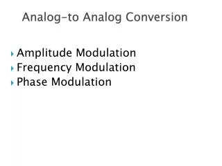
Angle Modulation • Effect of additive noise on modulated FM signal • Amplitude Modulation vs Angular Modulation • Importance of zero-crossing -> instantaneous frequency • Approximate • Block diagram of the receiver
Receiver • Bandpass filters limits noise to bandwidth of modulated signal • n(t) is bandpass noise Or, in Phasor form where Angle Demodulator Lowpass Filter Bandpass Filter 11
Phasor Analysis • Assumption:
Solve for SNR • Found demodulated signal y(t) • Composed of signal and additive noise • Assumption: m(t) is a sample function of a zero mean stationary Gaussian process with autocorrelation function RM(τ). • What about ? Recall: