TGC Timing Adjustment
This document provides a comprehensive overview of the timing adjustment techniques used in the TGC (Thin Gap Chamber) Trigger System, as presented by Chikara Fukunaga at the TMU ATLAS Timing Workshop on July 5, 2007. Key aspects covered include the structure and functionality of the Level 1 end-cap muon triggers, the role of electronics in timing signals, and methodologies for BCID (Bunch Crossing Identifier) alignment. The document also addresses the needs for monitoring, data quality, and event counting in the system, emphasizing the significance of precise timing in high-energy physics experiments.

TGC Timing Adjustment
E N D
Presentation Transcript
TGC Timing Adjustment Chikara Fukunaga (TMU) ATLAS Timing Workshop 5 July ‘07
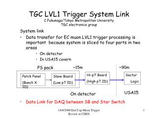
TGC Trigger System • TGC1(Triplet), 2 and 3 (both doublets) are used to provide the Level1 end-cap muon triggers (Main system). • The main system covers 1.05~2.4 of eta, and 100% of phi. • Inner chambers EI/FI (doublets) will be used to eliminate tracks not coming from the IP. • Wire (r) and Strip (phi) readouts. Both signals are used for the triggers.
2 for EI/FI/side 3 for SL/side,12 for ROD Overview of TGC Electronics System
Sector Electronics • 1/12 Sector is a unit for on chamber electronics (Two trigger sectors). • A sector has two identical electronics units. • Two geometrically identical sectors for triplet (M1) and doublets (M2,M3) • TTCrq on a Service Patch Panel • It distributes BC,L1A,BCR,ECR etc. to PS boards (ASIC PP, SLB) with equidistant cables. • One TTCrq distributes the signals also to HpT and SSW modules in Mini-crate
Adjustment of L1-buffer depth • Adjustment of Depth of Level1 buffer (128 steps) • The L1A latency will be common for cosmic and beam runs if the MUCTPI-CTP latency is fixed. • Even if the Latency changes, we can quickly re-adjust the depth with this setup.
BCID • TTCvi forms the BCR from the Orbit. • The delay capabilities for the BCR We have independent L1 buffer for BCID in the SLB ASIC. TTCvi for ROD. • 12-bit BCID you form is always in the range of 0..3563? Front-end system counts up to 4095 if BCR does not come properly.ROD will handle the BCID correctly in between 0 and 3563. • BCID checking : Consistency of Front-end BCIDs are checked in ROD • A global BCR delay parameter : TTCvi • Can the last 3 bits of the BCID be aligned with the BCID in the MUCTPI? : Reconfiguration of FPGA in Sector Logic
BCID Alignment • Are you ready for BCID alignment for the M4 week? What needs to be done still? • We can adjust the BCID of the front-end system by changing the depth of the BCID L1 buffer. This is ready. • As ROD independently counts BC, the number will be different from one of the front-end system even for the same L1A. We have to check the difference (offset) and adjust BCR timing or the depth of the L1 buffer for BCID iteratively. We need some more work, but will be ready for the M4 week.
Long Gap and Sensitivity to Bunch drift • We have not yet any fixed plan to do in the long gap. We need some more discussion for possibility of calibration for the system/detector in this gap. • ROD needs one test pulse trigger, generated by the CTP, in the long gap which is assigned to the TGC. • Sensitivity to slow drift of the bunches wrt to the clock.We have to estimate this in near future.
Event Count Reset • Distribution of the ECR: standard TTC partition • Where do you have event counters, where do you form L1ID ? SLB ASIC on a PS-board for the Front-end System, and ROD • Would you agree to set the ROD to the initial L1ID (0x00ffffff) in the prepareForRun transition? A register in the ROD module can be set to whatever is wanted. • Do you need any ECR before or after prepareForRun? If so, for which purpose, and at what time? Should this ECR be provided centrally, or can it be generated locally?One ECR is needed before the first trigger of a run. This siganl can be provided either centrally or locally.
Monitoring and Data Quality • Monitoring of the distribution of timing signalsWe have not yet fixed idea for this monitoring. • Where do you have L1A counters that are/could be published to IS?The ROD crate processor reads the counters kept by the ROD and publishes them to IS. • What's your view on L1ASync events?ROD will do L1ID checking withL1ASync events. • What tools could be used online/offline to check that the global timing is correct?The ROS or Event Builder should be able to check that the BCID/L1ID pairs from the detectors are what is expected by the CTP.