Hydronic Chilled Water System Applications and Design Principles
510 likes | 606 Vues
Learn about applications of hydronic chilled water systems, different pump designs, parallel pumping, and Domestic HW Recirculation Systems in a medical office building setting.

Hydronic Chilled Water System Applications and Design Principles
E N D
Presentation Transcript
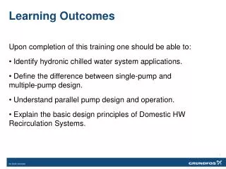
Learning Outcomes Upon completion of this training one should be able to: Identify hydronic chilled water system applications. Define the difference between single-pump and multiple-pump design. Understand parallel pump design and operation. Explain the basic design principles of Domestic HW Recirculation Systems. 1
Medical Office Building • Occupancy – 400 persons • 8 a.m. – 5 p.m. Monday - Friday • Building Characteristics • Three stories • 40,000 square feet (200’ x 200’) per floor • Standard construction
Hot Water Systems • Primary Pumps • Secondary Pumps • Tertiary Pumps • Heat Recovery Pumps • Air Handlers • Fan Coils • Radiant Floor • Convection Units • Filter Pumps
Boiler 2 Boiler 1 Hot Water Systems Fan Coils Radiators In-floor HWR P5 P5 CW Air Handler with Heat Recovery HW P3 P3 P3 P4 P2 Heat Exchanger P1 Type of Pumps P1 Primary P2 Secondary P3 Tertiary P4 Domestic HW P5 Heat Recovery P6 Filter P6 Filter System
Secondary Pumps ΔP Sensor Boiler 2* Boiler 1* VS/VV Hot Water Systems Supply VSP2* VSP1* P2* P1* VS Pumps and Controls Return *Multiple staged pumps
Chilled Water Applications • Primary Pumps • Secondary Pumps • Condenser Water Pumps • Fan Coils • VAV • Air Handlers • Chilled Beams
P4a P4 Chilled Water Applications Chilled Beams Radiant Fan Coils Type of Pumps P1 Primary P2 Secondary P3 Tertiary P4 Condenser Water P4a Condenser Water P5 Air Handlers P6 Filter Air Handlers P3 P3 P3 P5 P2 Cooling Tower OPTIONAL PHX Chiller Chiller Common Pipe Condenser Water P1 P1 Filter System P6 Expansion Tank Air Separator
CHW System Differences • Pumps are typically 3-4 times larger • Condensation concerns • Air separator location • Primary pump location • Open loop system piping
Parallel Pumping • Single pumps versus multiple pumps • Advantages • Common configurations
Higher HP No redundancy Less piping Less maintenance Less complicated Higher operating cost Lower HP Redundancy More piping More maintenance More complicated Lower operating cost Single vs. Multiple Pump Comparison Multiple Pump Design Single Pump Design
Parallel Pumping Common Configurations – Closed loop systems (2) 50% Duty Pump 100% Duty Pump 50% Duty Pump 50% Duty Pump 100% Standby Pump (1) 50% Standby Pump
2000 GPM 1000 GPM @ 100 Ft @ 100 Ft 1000 GPM @ 100 Ft 2000 GPM Parallel Pumping Parallel Pumps - What?
Parallel Pumping Parallel Pumps - Why? • Parallel pumping provides additive flow at the same point of head.
Pump Curve Point of Selection Single Pump Curve Head Flow
Single Pump Curve Parallel Pump Curve Duty Point Point of Selection Head Flow 1, Pump 2 Flow 1, Pump 1 • Flow Parallel Pump Curve
Parallel Pumping Parallel Pumps - Advantages • Smaller pumps • Smaller motors • Lower operating cost • Standby options • Right size pump operating more often
Parallel C/S 100 2 Pumps 90 80 Single C/S 70 60 50 % Full Load HP 40 30 Single Parallel 20 C/S 10 0 10 20 30 40 50 60 70 80 90 100 % Flow Parallel Pumping • Getting more out of your pump!
Parallel Pumping Operation Beyond Selection Point Pump 1 & 2 selection: 1000 gpm @ 100 ft Pump 1 selection: 500 gpm @ 100 ft Pump 1 operation: 820 gpm @ 68 ft System Curve
Parallel Pumping Review Selection Criteria • Select pumps for 50% of total flow (500 gpm, each) • Make sure each pump can cross system curve Parallel Pump Advantage • Pump runs out to 820 gpm • Operate one pump for ≥ 80%of the time • Save operational cost!
Parallel Pumping Cautions Improper parallel pump selection • Pumps too small • End of curve • Unequal sized pumps • Erratic operation
150 120 90 60 30 0 Pump 1 selection: 333 gpm @ 90 ft Pump 1& 2 selection: 666 gpm @ 90 ft Pump 1, 2, &3 selection: 1000 gpm @ 90 ft System Curve Head (ft) Pump 1 Pump 2 Pump 3 0 200 400 600 800 1000 1200 1400 Flow (gpm) Parallel Pumping Caution End of Curve
Parallel Pump Caution Unequal Size Pump Selection
Sequencing Parallel Pumps Pump sequencing methods: • Head • Differential Head • Temperature • Flow • Current sensing
40 35 30 25 20 15 10 5 0 P1 Head (ft) 0 100 200 300 400 500 600 700 Flow (gpm) Sequencing Parallel Pumps P1&2 Duty point Staging point
Parallel Pumping Parallel pumps - Operation • How many can you add? • Practical limit – 6 pumps
Maximum Number of Parallel Pumps P3 P2 P6 P7 P4 P5 P1
Parallel VS Operation Point D Point E Point C Point B Point A
VS/VV Pumping Add: • Variable frequency drive (VFD) • Programmable logic controller (PLC) • Differential pressure sensors (∆P) • Direct digital controls (DDC) Save operating cost versus CS/CV system!
CS/CV CS/VV VS/VV VS/VV Pump Energy Consumption
VS/VV Pumping Add: • Variable frequency drive (VFD) • Programmable logic controller (PLC) • Differential pressure sensors (∆P) • Direct digital controls (DDC) Or add…
Demand More Magna3!
Demand More – Intelligent Control Sequencing Parallel Pumps Traditional methods • Previously discussed
Demand More - Intelligent Control • Optimized solution not only for the pumps, but for the total system conditions • Uncontrolled (constant volume) curve • Constant pressure • Proportional pressure • Temperature control • FLOWADAPT • AUTOADAPT
Demand More - Intellegent Control 100 80 60 40 20 0 1. Effect in % H 2. 3. HEAD 4. 5. 0 20 40 60 80 100 25% 100% Q Flow in % Flow in % Get Additional Energy Savings • Uncontrolled • Constant pressure • Proportional pressure (calculated) • Proportional pressure (measured) • Temperature control
Recirculating systems compensate for the heat loss from water heater to last fixture DHW Recirculation Systems 41
DHW Recirculation Systems Use ASPE Domestic Water Heating Design Manual as a design reference 42
Three types of systems: Self-regulating heat trace system Point of use water heater Recirculating systems DHW Recirculation Systems 43
Determine wait time Calculate heat loss Calculate piping pressure drop Determine control method Select pump Check local codes DHW Recirculation Systems Design Criteria: 45
DHW Recirculation Systems More immediate desired hot water temperature at the tap Decrease Legionnaire concerns Reduce water consumption 46
DHW Recirculation Systems No specific national code requirements – some local codes >100’ length rule is no longer valid since both energy and water use have become important Length of time has increased due to low flow fixtures Older faucets: 2.2 GPM (prior to 1992) Low flow faucet: 0.5 GPM ½” pipe: 0.01 gallons/foot Run time to empty 100’ length of ½” pipe – Old faucet: 27 seconds Low flow faucet: 2 minutes 47
DHW Recirculation System Consider the delay time for HW 0-10 seconds for public fixtures in office buildings 11-30 seconds marginal but acceptable >31 seconds unacceptable (significant waste of water and energy) Max. distance ~25’ between the HW loop & the fixture Calculated length based on pipe size and distance 48
ASHRAE Standard 90.1-2010 section 7.4.4.4 requires circulating pump controls limiting operation to a maximum of 5 minutes after the end of the heating cycle. Control Options Manual control Thermostatic aqua-stat Time clock Also consider other local code requirements DHW Recirculation Systems 49
Pump Characteristics Because of the corrosiveness of open loop systems the pumps should be all bronze or stainless steel Make sure the pump’s casing pressure rating is higher than the relief valve DHW Recirculation Systems 50