INTERMEDIATE PRESSURE SYSTEM
INTERMEDIATE PRESSURE SYSTEM. PRESENTED BY: Dr CHITTRA MODERATED BY: Dr JYOTI PATHANIA. The intermediate pressure system receives gases from the pressure regulator or the pipeline inlet to the anesthesia machine. COMPONENTS. pneumatic part of the master switch pipeline inlet connections

INTERMEDIATE PRESSURE SYSTEM
E N D
Presentation Transcript
INTERMEDIATE PRESSURE SYSTEM PRESENTED BY: Dr CHITTRA MODERATED BY: Dr JYOTI PATHANIA
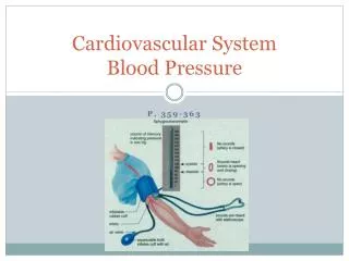
The intermediate pressure system receives gases from the pressure regulator or the pipeline inlet to the anesthesia machine
COMPONENTS • pneumatic part of the master switch • pipeline inlet connections • pipeline pressure indicators • piping • gas power outlet • oxygen pressure failure devices • oxygen flush • pressure regulators • flow control valves
pneumatic part of master switch • downstream of inlets for cylinder and pipeline supplies • master switch may be totally electronic that when activated controls the various pneumatic components of the anesthesia machine
pipeline inlet connection • pipeline inlet connection is the entry point for gases from the pipelines • Mandatory N2O and O2, usually have air and suction too • Inlets are non-interchangeable due to specific threading as per the Diameter Index Safety System (DISS) • unidirectional valve to prevent reversed gas flow • filter with a pore size of 100 µm
pipeline pressure indicator • present on panel on front of machine and may be color coded • On some newer electronic machines, LEDs indicate pipeline pressure • The workstation standard requires that indicator be on the pipeline side of the check valve in the pipeline inlet • If the indicator is on the pipeline side of the check valve, it will monitor pipeline pressure only • If the indicator were on the machine side of the check valve, it would not give a true indication of the pipeline supply pressure unless the cylinder valves were closed • pressure should be between 50 and 55 psig
PIPING • must be able to withstand four times the intended service pressure without rupturing • anesthesia workstation standard specifies that leaks between the pipeline inlet or cylinder pressure reducing system and the flow control valve not exceed 25 mL/minute • If yoke and pressure reducing system are included, the leakage may not exceed 150 mL/minute
GAS POWER OUTLET • may serve as the source of driving gas for the anesthesia ventilator or to supply gas for a jet ventilator
Oxygen failure safety device • whenever the oxygen supply pressure is reduced below the manufacturer-specified minimum, the delivered oxygen concentration shall not decrease below 19% at the common gas outlet
oxygen failure cut off valves(fail-safe) • A Fail-Safe valve is present in the gas line supplying each of the flowmeters except O2 • This valve is controlled by the O2 supply pressure and shuts off or proportionately decreases the supply pressure of all other gasses as the O2 supply pressure decreases • 2 kinds of fail-safe valves Pressure sensor shut-off valve (Ohmeda) Oxygen failure protection device (Drager)
pressure sensor shut off valve • The valve is threshold in nature, and it is either open or closed • Oxygen supply pressure opens the valve, and the valve return spring closes the valve • nitrous oxide pressure-sensor shut-off valve has a threshold pressure of 20 psig • oxygen supply pressure greater than 20 psig is exerted on the mobile diaphragm • This pressure moves the piston and pin upward, and the valve opens. • oxygen supply pressure is less than 20 psig, and the force of the valve return spring completely closes the valve • Nitrous oxide flow stops at the closed fail-safe valve, and it does not advance to the nitrous oxide flow control valve
oxygen failure protection device • OFPD interfaces the oxygen pressure with that of other gases • based on proportioning principle • pressures of all gases controlled by OFPD decrease proportionally with the oxygen pressure • consists of seat-nozzle assembly connected to spring-loaded piston • There is a continuum of intermediate configurations between the extremes of oxygen supply pressure • These intermediate valve configurations are responsible for the proportional nature of the OFPD
The oxygen supply pressure is 50 psig on left panel, pushes the piston upward, forcing the nozzle away from the valve seat • Nitrous oxide advance toward the flow control valve at 50 psig • The oxygen pressure in the right panel is zero psig • The spring is expanded and forces the nozzle against the seat, preventing flow through the device • Finally, the center panel shows an intermediate oxygen pressure of 25 psig • The force of the spring partially closes the valve • The nitrous oxide pressure delivered to the flow control valve is 25 psig
The oxygen ratio monitor controller (ORM [newer] or ORMC, both by Dräger) shuts off nitrous oxide when oxygen pressure is less than 10 psi • The newest Dräger machine, the Fabius GS, uses a Sensitive Oxygen Ratio Controller (S-ORC) • It's fail-safe component shuts off nitrous oxide if the oxygen flow is less than 200 mL/min, or if the oxygen fresh gas valve is closed.
oxygen supply failure alarm • whenever the oxygen supply pressure falls below a manufacturer-specified threshold ,usually 30 psig , at least a medium priority alarm shall be activated within 5 seconds • They aid in preventing hypoxia caused by problems occurring upstream in the machine circuit • These devices do not offer total protection against a hypoxic mixture being delivered, because they do not prevent anesthetic gas from flowing if there is no flow of oxygen • Equipment problems or operator errors that occur downstream are not prevented by these devices • do not guard against accidents from crossovers in the pipeline system or a cylinder containing the wrong gas
second stage pressure regulator • Some machines have pressure regulators in the intermediate pressure system just upstream of flow indicators • These receive gas from either the pipeline or the pressure regulator and reduce it further to around 26 psi for nitrous oxide and 14 psi for oxygen. • purpose of this pressure regulator is to eliminate fluctuations in pressure supplied to the flow indicators caused by fluctuations in pipeline pressure. • not present in every workstation
Most Ohmeda machines have a second-stage oxygen pressure regulator set at a specific value ranging from 12 to 19 psig • Oxygen flowmeter output is constant when the oxygen supply pressure exceeds the set value • pressure-sensor shut-off valves are set at a higher threshold value (20–30 psig) • ensures that oxygen is the last gas flow to decrease if oxygen pressure fails
oxygen flush • oxygen flush receives oxygen from pipeline inlet or cylinder pressure regulator and directs a high unmetered flow directly to the common gas outlet • The anesthesia workstation requires that oxygen flush be a single-purpose, self-closing device operable with one hand and designed to minimize unintentional activation • flow of 35 to 75 L/minute must be delivered
its activation may or may not result in other gas flows being shut off • may result in either a positive or negative pressure in machine circuit. • pressure is transmitted back to other structures in machine, and may change the vaporizer output and the flow indicator readings • The anesthesia workstation standard requires that the connection of the flush valve delivery line to the common gas outlet be designed so that activation does not increase or decrease the pressure at the vaporizer outlet by more than 10 kPa or increase the vapor output by more than 20%
HAZARDS • accidental activation and internal leakage • flush valve may stick in ON position • Barotraumaand awareness • activation during inspiration delivered by the anesthesia ventilator results in delivery of high tidal volumes and hence barotrauma may occur.
flow adjustment control • regulates flow of oxygen, air, and other gases to the flow indicators • mechanical and electronic • anesthesia workstation standard requires that there be only one flow control for each gas • must be adjacent to or identifiable with its flowmeter
mechanical flow control valve controls rate of gas flow through its associated flowmeter • COMPONENTS • BODY • STEM AND SEAT
CONTROL KNOB • control knob is joined to the stem • oxygen flow control knob is fluted and large • All other flow control knobs must be round • Accidental changes in position can also be minimized by a shield, bar, or other protective barrier and by placing them high above the working surface to lessen the likelihood of contact with objects on that surface
knob should be turned clockwise only until the gas flow ceases • Further tightening may damage to the pin or seat • Sometimes, flow control valve remains open when the machine is cleaned or moved • If gas supply to open flow control valve is restored and associated flow indicator is not observed, indicator may rise to top of the tube where its presence may not be noticed • the sudden indicator rise may damage it and impair the flowmeter accuracy
Flow control valves should be closed when not in use • If there is no yoke plug or cylinder in the yoke or the one-way valve in the pipeline inlet does not work well, gas from an unused gas system could flow retrograde through a flowmeter with an open flow control valve and leak to atmosphere • The stem or seat can block the flow
electronic flow control device • Electronically activated flow control devices can be used to alter gas flows • knob is turned clockwise to increase the flow • flow adjustment may utilize a solenoid valve • usually a mixing area collects the gas mixture • one control alters oxygen concentration and another control the total flow • If less than 100% oxygen is desired, the difference is made up from the second gas • Flow and pressure transducers as well as temperature sensors are used to maintain accuracy