Download
1 / 10
100 likes | 220 Vues
This detailed report discusses optimum LV ranges, safety rules, and stabilization times for HV systems. It also covers maximum accepted voltages for components and comparisons with Drake team results.

E N D
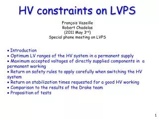
HV constraints on LVPS François Vazeille Robert Chadelas (2011 May 3rd) Special phone meeting on LVPS Introduction Optimum LV ranges of the HV system in a permanent supply Maximum accepted voltages of directly supplied components in a permanent working Return on safety rules to apply carefully when switching the HV system Return on stabilization times requested for a good HV working Comparison to the results of the Drake team Proposition of tests 1
Introduction • The sensitivity of the HV working with respect to the requested Low Voltages • has been reported in a Tilecal commissioning meeting in 2008 ( May 8th), • but it does comply with a permanent working, and not for a transitory status. • https://indico.cern.ch/getFile.py/access?subContId=8&contribId=0&resId=1&materialId=slides&confId=32923 • These results took also into account some safety margins of electronical • components. • We will remind very shortly these results that guarantee a good HV working. • Then we will give the upper voltages that the supplied components can accept • without damages. • We will remind the safety rules to apply when switching off/on the HV system, • and too the interest of waiting for stabilization times. • Then we will explain why the comparison with the Drake team results • is not yet straightforward. • Finally, we will propose to agree on a strategy for the next tests at CERN. 2
Optimum LV ranges for the HV system in a permanent supply The requested nominal values are given in the first columnof the Table 1. The study (reminded before) enabled to define the optimum ranges of each value for a working in a permanent regime: they are given in the second column. Table 1: Optimum ranges of LVs This concern is only with respect to the applied LVs. Other concerns should be considered about the working stability like the stabilization time, the humidity, the temperature… but it is not this concern. 3
Maximum accepted voltages of directly supplied components in a permanent working Table 2: For a theoretical supply at 5 volts Table 3: For a theoretical supply at 15 volts 4
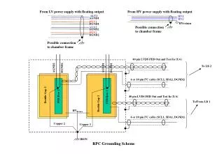
Return on safety rules to apply carefully when switching the HV system Table 4: Safety rules in the switching of the HV system Return on stabilization times requested for a good HV working • Two stabilization times play an important role: • The stabilization time of the HV electronics itself. • The stabilization time of the corresponding PMTs. • Depending from the components and PMTs, these durations are variable • and can go up to 10 hours and even more. 5
Comparison to the results of the Drake team Drake team results with respect to the HV part Table 5: Results about the overshoots and drops COMMENT and QUESTIONS: ●What is called ″nominal″ in this Table is not the official nominal values which are the “theoretical values” of the first column. ● What are the dispersions on overshoot and drop results ? Were they obtained from many bricks ? 6
Comparison of Table 5 with the specifications in a continuous regime • Specifications on the optimum ranges of Table 1 • - For the 15 V: applying 14.5 and 14.36 V give overshoots close to the upper • limit of 17 V. It should be increased if the theoretical values were applied. • This effect should be enhanced if the applied values were in the allowed • range [15, 17]. • For the + 5 V, the overshoot exceeds the upper limit. So a good HV working • is not guaranteed. It should be enhanced if we apply the allowed values • going up to 5.5 V. • - For the 15 V, the drops stay above the lower limit, but could be below • while applying a lower voltage within the optimum range down to 12 V. • For the + 5 V, the drop is close to the lower limit of 4.5 V: a small • decrease of the applied voltage (allowed down to 4.5 V) should lead below • this limit. However, if we forget the possible damages to the components (see next slide), it would be not a major problem to have a bad HV working during a short time of some ms. Besides, as this conclusion is based on a permanent regime, it would be not better during the short times of overshoot and drop. 7
Specifications on the maximum voltages of Tables 3 and 4 • For the 15 V, applying 14.5 V to MAX 536 gives an overshoot close to the • acceptable limit, and above if the theoretical value are applied. • If the allowedrange is used above (from 15 to 17 v), MAX 536 and INA128 can • be outside the acceptable limit. • So there is a risk of damaging these 2 components. • For 5 V, the risks are increased forMC68336 and MAX 233 because the • overshoot is reaching 6.77 V. It is the case of all the other components • (but for 82C250) if the maximum theoretical value of 5.5 V is applied. Comment: MAX 233 is only used by experts when they have to test the electronics. Thus if it is damaged, it will not prevent directly the HV working but could have an induced effect on it. The overshoots are capable of destroying most of the supplied components, these risks being increased by using the recommended theoretical values, and still enhanced by setting higher voltages (even though they stay within the optimum ranges of the Table 1). 8
In a first conclusion, based on the studies of a HV working in a permanent regime: • The HV working could be disturbed by the overshoots and undershoots, • but it is likely not a major problem because it stands during a very short time, • well below the stabilization times requested by HV working. • The main risks are about the overshoots being above the maximum allowed • values of most of the components, • but is it really dangerous during a short time ? WARNING: Are we sure that these kinds of overshoots and/or undershoots did never occur… in the present LVPS ? 9
Proposition of tests Only systematic tests at CERN (Building 175) should allow to conclude. So the proposition is as following: Using a multimeter, to check the applied LV’s. To repeat a big number of times the switching OFF/ON of the LVPS and HV systems, by following carefully the recommendation rules about the orders of commands: -Many times without setting ON the HV but reading only the DCS status. - From time to time (1 over 10 times), set ON the HV and check the HV values, without waiting for the stabilization time, in order to check only that the HV system is physically working. 3. The survey of the Microcontroller MC68336 is particularly important: in the worst case, it could be destroyed. In other cases it could give no reply: in such a case, the DCS is the best way to check it. The damages could occur also on other components. 4. These tests must repeated using several bricks and several drawers in order to take into account the dispersions of working of drawers and LVPS’s. 5. Clermont people are ready to contribute to these tests at the HV level. 10