Download
1 / 11
110 likes | 143 Vues
This workshop discussed Tilecal's upgrade with focus on safety factors, in-situ regulation, and possible improvements in electronics. Detailed specifications and performance reviews were presented for HV sources, distributors, and cards used in the system. Insights on radiation effects, system testing, and future enhancements were shared. Overall, the workshop aimed to enhance the performance and safety of the Tilecal system at CERN.

E N D
On Detector electronics: PMT HV system Tile Upgrade Workshop (CERN- February 2008 8 and 9) François Vazeille • Reminder about the Tilecal set-up Design, production and tests (Clermont-Ferrand) Specifications and performances • Reminder about safety factors on radiation effects • Possible improvements
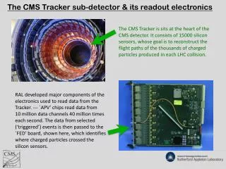
Reminder about the Tilecal set-up … and about the individual regulation loop • Tilecal in-situ regulation • Based on one Optocoupler chip/channel • Use of an external HV (common to 24 Channels) located in USA15 room HV out Opto coupler From DAC • Loop working stand-alone once the DAC value is set by the user via the DCS (…even though the DCS is lost or if the HV Micro is dead) From HV Source
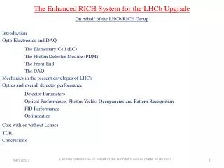
… and about the general set-up in the pit 2 main elements: - HV Source (USA15) - HV Distributors (UX15) USA15 HV PC LVCAN PC + Associated elements and connections: - CANbus and LVCAN PS (and LVCAN PC) - DCS: HV PC + CAN interfaces - fLVPS HV Source LVCAN Patch P Internal HV Bus Flex Bus External HV bus Long cable Internal HV Opto External HV Opto HV Micro fLVPS Short cable HV Distributors of Super-Drawer (6 cards/Super-Drawer) Daisy chain Comment: LVCAN Power Supplies separated for HV and the Integrator ADC It is an advantage for me because the 2 systems are very different.
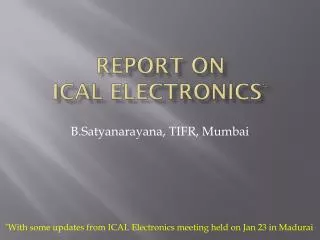
HV Distributors • 5 types of cards - Bus cards: Stiff Internal, Stiff External, Flexible • - Opto cards (Optocouplers) • - Micro cards (Microcontrollers) • The Microcontroller (MC68376) plays 2 roles: - Control of the Opto and Micro cards - CANbus Interface (with a LV regulator powered by a CANbus PS) Bus cards: 270 Stiff Internal 270 Flexible 270 Stiff External 90x1310 mm2
110x600 mm2 100x170 mm2 540 Opto cards + other spares 270 Micro cards + other spares + Making and use of dedicated Test Benches for each type of cards, several times used before, during and after burn-in + Drawers Test Benches +In particular: Very Long Term Test of Opto cards (Full Daisy chain) associating HV Distributors and HV Source Specifications and performances • Specifications: (HV) < 0.5 V in order to have G/G < 0.5% on PMTs • Performances: (HV) < 0.1V from Clermont-Fd, Test Beam and Pit results Comment: some induced noise on the readout. Proper to any HV system and due to the whole front-end scheme but that does not mean that improvements could not be made in the future.
Reminder about safety factors on radiation effects Studies (Tilecal notes) made about: - TID and NIEL doses on cmos and bipolar components - SEE TID: Total Ionizing Dose NIEL: Non Ionizing Energy Loss SEE: Single Event Effect • ATLAS rules on safety factors
We will consider 3 steps: - Nominal Luminosity: 1034 - Ultimate Luminosity: 2.3 1034 - Ultimate SLHC: 10 1034 Tables of safety factors as requested and as measured (worst location), for 5 years running in each scenario TID • - For the HV Opto: it affects generally 1 channel only. • - New tests for bipolar could be requested if the required safety stays at 70, • because of the large uncertainty on simulations (Factor 3.5) • The first ATLAS radiation results will bring useful information.
NIEL Quoted in parenthesis: pre-prod components - For the HV Opto: it affects generally 1 channel only. - New tests could be requested if the required safety stays at 50, because of the large uncertainty on simulations (Factor 5) The first ATLAS radiation results will bring useful information. SEE from tests equivalent to 10 years at 1034 - Latch-up effect: on one Micro card inducing Zero voltage/week Recovered by a power cycle of the Tilecal affected component (here the Super-Drawer) once per day (as foreseen for the whole Tilecal) Comment: 3 SEU per minute in the whole Tilecal - No destructive SEU during the tests: What would be the results at a higher luminosity? The first ATLAS results will bring useful information, in particular about the large simulation factor (5). Conclusion: no so far about radiation effects First ATLAS results waited.
Possible improvements … always possible once the experience comes at the full scale from the whole detector … Why an in-situ regulation? • To optimize both the regulation close to the channels and the noise effects • (no pick up on very long cables) • + separation of HV side and readout-side. - To save money: no equivalent commercial product. Possible improvements from the most important to others • The most important: direct link with fLVPS (mainly a hardware link), • in particular in case of a destructive SEU. - New HVFLEX (already found … but expensive). - Noise killers integrated in the cards on every channel (HVBus or HVOpto). • Better optimized design of the HV tracks on the HVBus boards • (Possible source of noise). - Individual switches (And not 1 for 12 channels) … but more expensive.
BUT some components would become obsolete if too many things were changed! • Why not taking benefit of Micro-electronics? • Why not using rad-hard components? But cost! Are there alternative solutions? - Everything in the counting room? • Come back to the starting point: - Space in USA (Take as reference the volume of Prague HV Source) - 10 000 long cables - Noise problems - Cost if commercial unless moving the present HV Distributors in USA15 ? … - Everything in the cavern but outside the Modules? The worst solutions: radiations higher than in the Girders.
First conclusions • We need to know better the whole HV system, including the HV Source and the fLVPS + the CANbus PS in order to finalize the specifications of what could be a perfect system. • So we must execute the HV Commissioning as foreseen in the WP10 possibly by revising it (My job in the next weeks). • We are not very far from what would be needed at the radiation level and the ATLAS running will provide very useful information on: • - The true radiation levels Safety factors revised. • - The behavior of the HV system. New radiation tests will be likely requested. • It is not clear that an upgrade should be needed, even though some weak points would stay. A medium solution could be a smooth upgrade: the most important points, without remaking everything, saving time and money.