Download
1 / 24
250 likes | 387 Vues
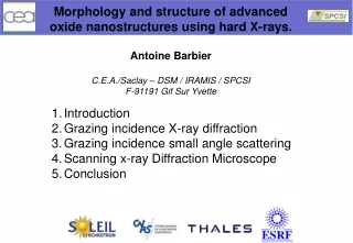
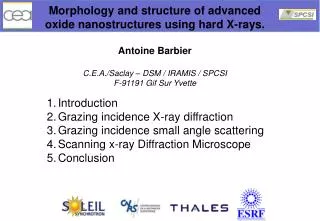
Morphology and structure of advanced oxide nanostructures using hard X-rays. Antoine Barbier C.E.A./ Saclay – DSM / IRAMIS / SPCSI F-91191 Gif Sur Yvette. Introduction Grazing incidence X-ray diffraction Grazing incidence small angle scattering Scanning x-ray Diffraction Microscope

E N D
Morphology and structure of advanced oxide nanostructures using hard X-rays. Antoine Barbier C.E.A./Saclay – DSM / IRAMIS / SPCSI F-91191 Gif Sur Yvette • Introduction • Grazing incidence X-ray diffraction • Grazing incidence small angle scattering • Scanning x-ray Diffraction Microscope • Conclusion
1. Introduction - Context MRAM chip (IBM) FM1/Insulator/FM2 Generation of a spin polarized current Array of micron sized structures obtained by lithography - High areal density - High current densities for writing Spin-filter effect GMR, TMR… GMR : Nobel Prize 2007 : Albert Fert and Peter Grünberg
ReciprocalspaceExample : NiO(111) type surface 20L 00L 10L Bulk Bragg peaks 02L 22L Specular CTRs Þ relative position vs. bulk 01L 11L 21L 2,2,3/2 AF mesh 12L 0,0,3/2 Magnetic Bragg peaks (Antiferromagnet) h00 2,2,1/2 GISAXS Bulk mesh (2x2) mesh 0k0 In-plane diffraction Þ Projected 2D structure Reconstruction diffraction rods Þ ^ relaxation and thickness
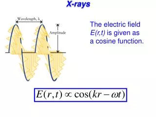
Grazing incidence X-ray scattering • Complex refraction index of X-rays : Reciprocal space Real space with q ^ • If n £»1 then q // Z (L) Y (k) X (h) r q r r k q a ^ i i r r q k / / q a f f 2 q Insensitive to charge build-up – Very sensitive to surface through grazing incidence – Requires synchrotron radiation
GIXD on MgO(111) Air 1500°C/3h annealed surface GIXD, RT, 17 keV, @ ID03, ESRF RT 254°C Simple monoxide without electronic correlations DFT calculations possible • R.Plass et al. PRL 81 (1998) : Cyclic Ozone • Electrostatic ??? • Diverging surface energy Es (octopole) =2.05 J/m2 Es (spinel) =4.45 J/m2 (metastable !!!) Es (1x1) =5.6 J/m2 Es (ozone)> Es (1x1) (unstable !!!) Role of oxygen potential ??? F.Finocchi, A.Barbier, J.Jupille, C.Noguera PRL 92 (2004) 136101 A. Barbier et al., J. Phys.: Condens. Matter 20 (2008) 184014
GIXD on MgO(111) Air 1500°C/3h annealed surface RT – 28% O-Oct 520K – 13% O-Oct Numerical relaxation of structures Relative fraction = Only fitting parameter Reproducing the GIXD structure factors (150K - 320K) + Satisfy the electrostatic criterion + Minimising surface energy + Taking into account the oxygen potential (grand canonical) O-octopole + Mg/MgO(111)
GIXD on MgO(111) Role of oxygen chemical potential @ ESRF, ID03 Patterson (self-correlation) maps vs O MgO(111) surface termination depends on chemical environement A. Barbier et al., J. Phys.: Condens. Matter 20 (2008) 184014
GIXD on -Fe2O3(0001) Role of oxygen chemical potential @ ANKA Reduction – re-oxidation cycle Surface structure changes (irreversible) A.Barbier et al. Phys. Rev. B 75 (2007) 233406
Small angle X-Ray Scatteringin situ deposition Ag/MgO(001) Co/Au(111) Geometry - Principle Ag/MgO, Co/Au : G. Renaud et al., Science 300, 1416 (2003) NiO/Cu(111) : A. Barbier et al., Phys. Rev. B 68 (2003) 245418 Coalescence Self-organized CNTs : J. Mane-Mane et al., PSSRRL 1(2007)122 & PSS(a) 204(2007)4209
GISAXS – ModelisationSelf-patterning : NiO/Cu(111) NiO/Cu(111) 0.3, 5.4, 8.3, 9.0, 9.8, and 10.8 Å Self-organization above 6 Å 80nm x 80 nm Reactive interface => islands + hole creation due to Ni-Cu corrals A. Barbier et al., Phys. Rev. B 68 (2003) 245418
GISAXS – Island shape investigationsRh/MgO(001) From P. Nolte et al., Science 321, 1654 -1658 (2008) Islands shape changes can be recorded upon oxidation / reduction cycles => Catalytic activity cannot be extrapolated from UHV observations only
Principle of a “Scanning x-ray Diffraction Microscope“ Setup available @ ID01 (ESRF) C. Mocuta et al., Phys. Rev. B 77, 245425 (2008)
Compound Refractive Lenses (CRL) singlelens Snigirev et al, 1996 stack of lenses: compound refractive lens (CRL) variable number of lenses: N=10 -300 R = 200 mm 2R0 ~ 1 mm d ~ 5 mm F(1 lens, 10 keV) = 29.3 m Gain ~ 30 F(50 lenses, 10 keV) = 0.6 m Gain ~ 3×10⁴ Here : E=7 keV, 18 CRL, F = 800 mm Spot size of about 69 m² (HV)
MBE growth of Pt/CoFe2O4/Al2O3/Co MTJs Reciprocal lattices (0,2) (1,1) Knudsen cell Plasma source (1/2, 1/2) Fe + Co (0,1) a* b* Oxygen D1 D2 a-Al2O3 (0001) Fe3O4 (111) or CoFe2O4 (111) Co In situ RHEED characterization Reflection high energy electron diffraction Oxygen plasma-assisted molecular beam epitaxy g-Al2O3 (111) Growth on α-Al2O3(0001) substrate CoFe2O4 Co (0001) g-Al2O3 (111) Pt CoFe2O4 (111) Pt (111) α-Al2O3 (0001)
SamplesLithography CNRS/Thales Full lithography with contacts Partial lithography with junctions of variable shapes Lithography of structures alone Spin filter Al2O3(0001)/Pt(10nm)/CoFe2O4(5 nm)/-Al2O3(1.5 nm)/Co(15 nm) /Au(15 nm) MTJ Al2O3(0001)/Pt(10nm)/Fe3O4(25nm)/-Al2O3(3nm)/Co(15nm)/Au(15nm)
Sample crystalline structure Co(0002) Epitaxial + Single crystalline growth Continuous layers (incl. barrier) For each layer a given /2 setting layer selective analysis
Specular Intensity Mapping @ Bragg peaks Scanning probe microscope q Au Au Co Co CoFe2O4 Pt buffer CoFe2O4 Al2O3 substrate Pt Measure of the intensities The layer structure is resolved C.Mocuta et al., Appl. Phys. Lett. 91, 241917 (2007)
Bragg peak position mapping X X - - ray ray scattered scattered beam beam a a q q sample sample ( ( = = ) ) i i normal normal [001] [001] n n h h q q (2 (2 ) ) hx hx Co(002) // hz hz hz hz 1.6° Co(002) // hx 0.2° 0.6° 0.6° CoFe2O4 (20 x 20 m²) – Rocking scans depending on position CoFe2O4 (20 x 20 m²) Bragg peak max moves when scanning ║ beam Fwhm constant No effect beam Lattice deformation CoFe2O4 (20 x 20 m²) C.Mocuta et al., Eur. Phys. J. Special Topics 168, 53–58 (2009)
Square CoFe2O4 MTJ 50x50m Co(0002) Measure the tilt of the crystalline planes function of the lateral position in the junction Dq(x) = qBragg(x) – qBragg(center) Layer deformation is maximal for intermediate sized junctions like 20x20m² Effect decreases for the smallest junctions (0.3° for 10x10 m² junctions) : size effect
Fe3O4 based TMJ (Disk 50m) Co(004) 0.6° 0.3o Fe3O4(333) 0.3° q q-Dq q+Dq Au Co(004) Co Al2O3 50m Fe3O4 0.15o Pt buffer Al2O3 substrate Fe3O4(333) Co electrode is more affected Similar lattice deformation Reversed effect on max Different layer relaxation
Shape effect - Fe3O4 MTJs 3 2 1 0 angular shift (deg) o -1 q Co(004), 2 =120.6 B -2 120x40m x8 f m =50 m -3 1.00 0.75 peak area (arb.units) 0.50 0.25 0.00 -80 -60 -40 -20 0 20 40 60 80 m position from junction's center (T , m) y q q-Dq q+Dq Au 3o Co Al2O3 Fe3O4 0.9o Pt buffer Al2O3 substrate The deformation is shape dependent for a given material Circular objects experience less deformation (~1 order of magnitude !!!)
Lattice Parameter Evolution Lattice Parameters followed in situ by RHEED Fe3O4 Sample (CoFe2O4): Al2O3 not relaxed larger effect after lithography contraction ? Sample (Fe3O4): Al2O3 is relaxed smaller effect after lithography Tentatively it is likely that lithography promotes structural relaxation -Al2O3 A. Bataille, PhD Thesis (2005)
ConclusionsHard X-rays methods vs oxide nanostructures • Advantages : • No charge build-up problems • Investigation of real samples possible • Investigation under different sample environments • Non – destructive investigations • Large variety of methods available • Surface structure investigations • Island morphology and/or reactivity • Nanostructure structural relaxation, shape and size effects • Drawbacks • Synchrotron radiation often mandatory • Good crystalline structural required • Sometimes high photon density and /or focalization needed Thanks for your attention
Coworkers Polar oxides and MgO(111) Surface diffraction F.Finocchi, J.Jupille, C.Noguera, K. Peters, H. Kuhlenbeck, B. Richter, A. Stierle, N. Kasper, C.Mocuta GISAXS G.Renaud, O. Ulrich, O. Fruchart, S. Stanescu, J. Mane-Mane, R. Lazarri, J. Jupille, F. Leroy, Yves Borensztein, C. R. Henry, J.-P. Deville, F. Scheurer, C. Boeglin Scanning x-ray diffraction microscope C. Mocuta, A.V. Ramos, M.-J. Guittet, J.-B. Moussy, S. Stanescu, R. Mattana, C. Deranlot, F. Petroff