Download
1 / 19
200 likes | 489 Vues
Eddy Current Septum Magnet Optimization. Powering Options of SMH42 and the Influence of the Septum T hickness on the Fringe Field. Zsolt SZOKE (TE/ABT/SE). Outline. Eddy Current Septa Magnets Our Goal Baseline Design Performance Analysis in Time Domain

E N D
Eddy Current Septum Magnet Optimization Powering Options of SMH42 and the Influence of the Septum Thickness on the Fringe Field Zsolt SZOKE (TE/ABT/SE)
Outline • Eddy Current Septa Magnets • Our Goal • Baseline Design Performance • Analysis in Time Domain • Comparing Full Sine and Half Sine Excitation • Comparing 5mm and 3mm Septum Blades • Comparing 2ms and 7ms Wavelength LIU-PS Meeting
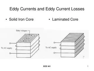
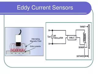
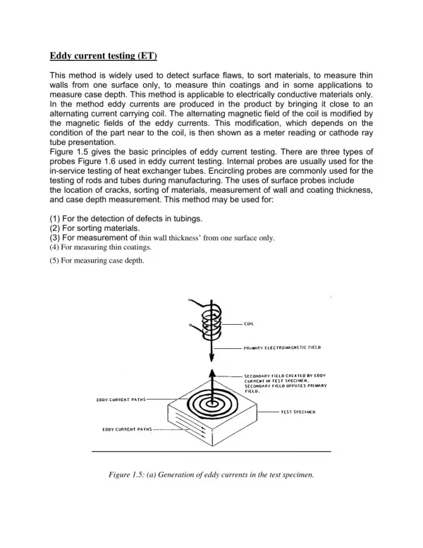
Eddy Current Septa Magnets • Different types of septa: • direct drive (DC, pulsed) • eddy current (only pulsed) • Eddy current type - advantages: • coil dimensions are not critical • the pulsed coil has such a magnetic field which induces eddy currents in the septum counteracting the fringe field • septum can be very thin LIU-PS Meeting
Our Goal • Optimize different eddy current septum magnet parameters. • 3 comparisons made with the baseline design. • Baseline: 2ms, full sine, 5mm septum. • Examination of the fringe field: By and ∫Bydl. 3mm septum 7ms half sine LIU-PS Meeting
Baseline Design Performance • ʃBy,gapdlmax = 502.67Tmm • By,gap,max = 542mT • ʃBy,fringedlmax= -1.37Tmm (after the current pulse) • By,fringe,max = -1.4mT (after the current pulse) • Idriving,max = 30251A • Gap fringe field shape: LIU-PS Meeting
Analysis in Time Domain (1/2) • Opera finite element simulation, spanning 3× the excitation time • Discrete moments interpolation in MATLAB • 2 types of interpolation: • PCHIP: for plotting • SPLINE: for peakdetermination LIU-PS Meeting
Analysis in Time Domain (2/2) • 6 values for each simulated moment: • t [ms] • I [kA] • By(gap) • ∫Bydl (gap) • By(fringe) • ∫Bydl (fringe) • “gap”: the middle of the aperture • “fringe”: 5mm from the septum LIU-PS Meeting
Comparing By of Full Sine and Half Sine • Fringe field extents after excitation. • Full sine: By = -1.4mT • Half sine:By = 15mT LIU-PS Meeting
Comparing ʃBydl of Full Sine and Half Sine • Integrated fringe field extents after excitation. • Full sine: ∫Bydl = -1.37Tmm • Half sine:∫Bydl = 14.28Tmm LIU-PS Meeting
Comparing Full Sine and Half Sine • Huge time constants in both cases: • 1 or 2ms excitation time (half or full sine) • time constant: >4ms • Fringe field peak values are 10.4-10.7 times lower using full sine wave instead of half sine. • Using ‘direct damping’ of the fringe field (full sine excitation) proves to be very effective. LIU-PS Meeting
Comparing By of 5mm and 3mm Septa • Fringe field extents after excitation. • 5mm septum blade: By = -1.4mT • 3mm septum blade:By = -3.6mT LIU-PS Meeting
Comparing ʃBydlof 5mm and 3mm Septa • Integrated fringe field extents after excitation. • 5mm septum blade : ∫Bydl = -1.37Tmm • 3mm septum blade :∫Bydl = -3.51Tmm LIU-PS Meeting
Comparing 5mm and 3mm Septa • A thinner septum blade is advantageous for the beam: lower continuous losses. • 3 mm septum blade has higher current density. • Fringe field peak values are 1.7-2.6 times lower using 5mm septum instead of 3mm. LIU-PS Meeting
Comparing By of 2ms and 7ms Wavelength • Fringe field extents after excitation. • 2ms wavelength: By = -1.4mT • 7ms wavelength:By = -15.6mT LIU-PS Meeting
Comparing ʃBydlof 2ms and 7ms Wavelength • Integrated fringe field extents after excitation. • 2ms wavelength : ∫Bydl = -1.37Tmm • 7ms wavelength :∫Bydl = -15.14Tmm LIU-PS Meeting
Comparing 2ms Wavelength and 7ms • 3.5 ms pulse half sine shape would be a pulse length similar to present SMH42. • Shorter pulse length (w.r.t. baseline design) wasn’t investigated, since it will be very difficult to build a compatible magnet. • Fringe field peak values are 3.2-11.1 times lower using 2ms full sine wave instead of 7ms. LIU-PS Meeting
Final Conclusion Full sine vs. Half sine Direct fringe field cancellation very effective 5mm septum vs. 3mm septum The thicker the septum, the lower the fringe field 2ms wavelength vs. 7ms wavelength The shorter the pulse, the lower the fringe field The base line design appears a good compromise. Next: the BMP42 septum bumper analysis. LIU-PS Meeting
References • Full documentation: Z. Szoke: Eddy Current Septa Magnet Optimization • M. J. Barnes, J. Borburgh, B. Goddard, M. Hourican, in Proceedings of the CAS-CERN Accelerator School: Magnets, Bruges, Belgium, 16-25 June 2009, edited by D. Brandt, CERN-2010-004, pp. 167-184 • Finite element simulations: Cobham Opera 16 • Data processing: MATLAB R2013b LIU-PS Meeting
Thank You for Your Attention!Q&A LIU-PS Meeting