Download
1 / 20
200 likes | 349 Vues
Target wheel eddy current modelling. James Rochford On behalf of the Helical collaboration. Carmen–Electra comparison. Description Having under stood the Electra solutions and gained some confidence in the solution a Carmen model was constructed which included the spokes

E N D
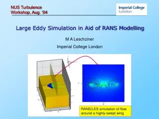
Target wheel eddy current modelling James Rochford On behalf of the Helical collaboration STFC Technology
Carmen–Electra comparison • Description • Having under stood the Electra solutions and gained some confidence in the solution a Carmen model was constructed which included the spokes • The CARMEN solver, has the capability to solve the full dynamic problem i.e the motion coupled to the electromagnetic solution and does not need any rotational symmetry in the problem. • A sacrificial mesh layer , “the gap” around the rotating region is re-meshed for all points in the solution • Meshing needs to be adequate to model current distribution and robust enough to allow the gap to be re-meshed at all points in the solution whilst giving consistent solutions Mesh distribution in wheel
Carmen–Electra comparison • Description • Having under stood the Electra solutions and gained some confidence in the solution a Carmen model was constructed which includes the spokes • The CARMEN solver, has the capability to solve the full dynamic problem i.e the motion coupled to the electromagnetic solution and does not need any rotational symmetry in the problem. • A sacrificial mesh layer , “the gap” around the rotating region is re-meshed for all points in the solution • Meshing needs to be adequate to model current distribution and robust enough to allow the gap to be re-meshed at all points in the solution whilst giving consistent solutions Mesh distribution in wheel
Carmen–Electra comparison • Model results; part revolution 0o-60 o • Run a number of Carmen solutions to look at the effect of step time on the problem solution • The effect of time not so critical can see step 2deg starts to deviate from 1deg solution- problem computationally very expensive. • In these solutions we see the force increases by a factor of 7 @ 100rpm w.r.t the Electra simple wheel rim prediction. • Is this real is it caused by the spokes? • Retarding torque predicted by CARMEN for 100rpm for a part revolution
Carmen–Electra comparison • Model results; full revolution • Here a full rotation is run But the solution step is every 2 deg but the mesh is slightly cruder • So solution not quite as accurate as part solutions • But you can clearly see 5 equally spaced peaks in the torque • Rem; wheel has 5 spokes • Between peaks Torque drops to a value comparable with the Electra solution. • Retarding torque predicted by CARMEN for 100rpm for a full revolution
Carmen–Electra comparison • Model results; full revolution • Here we see the torque peaks correspond to each point a spoke crosses the –ve X axis i.e. when a spoke passes through the coil centres 90o 162o 18o rotation 234o 18o 162o 234o 306o 90o 306o • Retarding torque predicted by CARMEN for 100rpm for a full revolution Alignment at t=0
Carmen–Electra comparison • Why does the torque increase? • The reason becomes evident once one looks at the eddy current distributions • What happens is the spokes rotate they create additional current paths, all the paths meet in the center and return via the central spoke it passes the coil centre. • This current gives rise to large Ix (~600A) along the spoke coupled to the BZ field generates a large Fy giving rise to a larger retarding torque. • In between the spoke transit the current distribution reverts to one similar that seen in the Electra models. In this case the currents down the spokes are ~80 amps and the torque generated by each spoke should cancel. I-1 I-2 I-0 I-3 I-4 I-0=I-1+1-2+I-3+I-4=590A I-1=I-4=265A 1-2=I-3=30A
Carmen–Electra comparison • Movie showing eddy currents a wheel rotates • Note the increase of currents in the R.H.S of the wheel as the spoke passes the coil centerline
Carmen–Electra comparison • Off axis torques Tx • By symmetry there should be no torque about the X axis. • This is what the models show
Carmen–Electra comparison • Off axis torques Ty • There may be a torque about Y causing the wheel to “jitter”. This could be generated by a nett Fz in the interaction region. • The models indicate there may be a significant Ty, • However the full revolution model (purple curve) seems to be too crude to resolve this, but the more accurate part revolution models seem to show something • It looks like we generate ~+(2-3)N.m as the spoke approaches the coil centre and switching to –(2-3)N.m as it recede from the coil centre • This is small @ 100rpm, and should scale with the speed, I would expect ~+/-(40-60)N.m @2000 rpm . • This is not huge, I may cause the wheel to jitter? • Additionally over time it may cause significant wear in wheel bearings, particularly at higher speeds?
Carmen–Electra comparison • Power dissipation • Whilst Electra predicts a power of 0.07kW to continually drive the wheel rim through the field @ 100rpm. • Carmen predicts additional power of 0.32kW is needed by the spokes as they pass through, creating peaks of .39kW. • This increases the average power to something like 0.2kW • i.e. more than double the Electra prediction
What happens at higher speeds? • Previous work to validity Carmen solution at lower speed • Now extent the model to look at Higher speeds • Look at the skin effect • Force predictions for higher speeds @ Bgap 0.485T • Power predictions for higher speeds @ Bgap 0.485T • Are previously suspected off axis forces significant • Greater immersion depths • In these model just the rim is immersed in the field • Need to quantify the effect of immersion depth
What happens at higher speeds? • Is the model adequate to replicate high speed operation • Is skin effect significant in models • Simple estimate of skin depth • 1/S(s.f.muo.mu.p) where • f=freq, muo=Magnetic permeability • mu =relative permeability, s=conductivity • Full field penetration of ring out to 6000rpm • Still significant dragging of the field • No special mesh considerations • Other mesh issues • Pecklet number • Insufficiently small mesh may prevent convergence in solution. • To avoid this need Pecklet number <1 • Mesh in outer region of wheel <4mm
What happens at higher speeds? • Predicted power dissipation @ different speeds • Models run for gap field of 0.48T • At 2000 rpm torque peaks at 7.7kWm
What happens at higher speeds? • Predicted power dissipation @ different speeds • Models run for gap field of 0.48T • At 2000 rpm power peaks at 7.7kWm
What happens at higher speeds? • Are off axis torques significant? • No indication of off axis torques • Would expect them to scale with speed • Don’t see this • Probably just a mesh error
What happens at higher speeds? Plot of Bz on field surface at 2000rpm Rotation • Is there significant field distortion at high speed • The field is dragged • this may be significant for beam\pair production? • There are two effects • general dragging related to speed • And a periodic distortion from spokes Field plots
What happens at higher speeds? Dragging as a function of speed • Field distortion by rim motion • The field is dragged • Normal cylindrical distrobution of Bz • Distorted along the direction of motion • This is constant at constant speed • So may not be a problem
What happens at higher speeds? • Field distortion by spokes motion • Get a periodic jitter in the field • This may be an issue for the beam pair production • Here see the effect of a spoke passing • @ 54 deg mid point between spokes • @ 90 deg spoke center passing • @126 deg next mid point between spokes • See here the field wobbles as the spokes pass 90o 162o 18o 234o 306o
What happens at higher speeds? • Additonal models to run • Running high speed models at higher field • The current models are at 0.485T • want to run 1 200rpm model at 1T as per ILC wheel • Quantify the effect of immersion depth • In these model just the rim is immersed in the field • 1-2 high field models with different immersion depths • Agreement between models and experiment