Eddy Current Sensors
Eddy Current Sensors. Eddy Current Sensors.

Eddy Current Sensors
E N D
Presentation Transcript
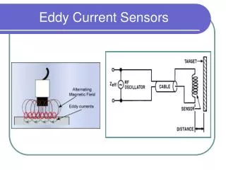
Eddy Current Sensors • An eddy current is a local electric current induced in a conductive material by the magnetic field produced by the active coil. This local electric current in turn induces a magnetic field opposite in sense to the one from the active coil and reduces the inductance in the coil. • When the distance between the target and the probe changes, the impedance of the coil changes correspondingly. This change in impedance can be detected by a carefully arranged bridge circuit. The eddy currents are confined to shallow depths near the conductive target surface. Their effective depth is given by:
Eddy Current Transducer • The target material must be at least three times thicker than the effective depth of the eddy currents to make the transducer successful. This is because the transducer assumes that the eddy currents are localized near the surface of a semi-infinite solid, and the actual eddy current amplitude decreases quadratically with distance. • In practice, the effective range of an eddy current transducer is given by the vendor suggested range offset from the target surface by 20%. For example, a 2.5 mm (0.1 in) range eddy current transducer is generally considered effective from 0.5 to 3 mm (0.2 to 1.2 in) from the target surface. • The targeted flat surface area should not be smaller that the probe tip diameter. If the target surface is smaller than 50% of the probe diameter, output signals decrease substantially.
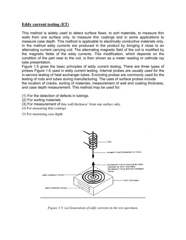
Linear Displacement Eddy-Current sensors operate with magnetic fields. The driver creates an alternating current in the sensing coil in the end of the probe. This creates an alternating magnetic field with induces small currents in the target material; these currents are called eddy currents. The eddy currents create an opposing magnetic field which resists the field being generated by the probe coil. The interaction of the magnetic fields is dependent on the distance between the probe and the target. As the distance changes, the electronics sense the change in the field interaction and produce a voltage output which is proportional to the change in distance between the probe and target.
Eddy Current Transducer The Eddy Current Transducer uses the effect of eddy (circular) currents to sense the proximity of non-magnetic but conductive materials. A typical eddy current transducer contains two coils: an active coil (main coil) and a balance coil. The active coil senses the presence of a nearby conductive object, and balance coil is used to balance the output bridge circuit and for temperature compensation.
Deflection of a cantilever A cantilevered beam can be used to illustrate environmental effects on eddy current sensor performance, sources of error, resolution, and versatility. The demonstration hardware consists of a simple cantilever beam constructed of rectangular aluminum conduit that has been black-anodized An eddy current sensor under the free end of the beam measures vertical deflection:
Applications…. position • Eddy-Current sensors are useful in any application requiring the measurement or monitoring of the position of a conductive target, especially in a dirty environment. • Eddy-Current sensors are basically position measuring devices. Their outputs always indicate the size of the gap between the sensor's probe and the target. When the probe is stationary, any changes in the output are directly interpreted as changes in position of the target. This is useful in: • Automation requiring precise location • Machine tool monitoring • Final assembly of precision equipment such as disk drives • Precision stage positioning
Application ….Dynamic Motion • Measuring the dynamics of a continuously moving target, such as a vibrating element, requires some form of noncontact measurement. Eddy-Current sensors are useful whether the environment is clean or dirty and the motions are relatively small. Eddy-current sensors also have high frequency response (up to 80kHz) to accommodate high-speed motion. • Drive shaft monitoring • Vibration measurements
Application …. Thread detection • The presence or absence of threads in a tapped hole is a major concern in the automotive and other industries. A simple untapped hole stops production lines and costs thousands of dollars an hour. Eddy-Current sensors, when inserted into a metal hole will provide different outputs depending on the presence or absence of threads.
Pros and Cons of E.C. Sensors • Pros: - • Non-contacting measurement. - • High resolution. - • High frequency response. • Cons: • Effective distance is limited to close range. • The relationship between the distance and the impedance of the coil is nonlinear and temperature dependent. Fortunately, a balance coil can compensate for the temperature effect. As for the nonlinearity, careful calibrations can ease its drawback. • Only works on conductive materials with sufficient thickness. It can not be used for detecting the displacement of non-conductive materials or thin metalized films. However, a piece of conductive material with sufficient thickness can be mounted on non-conductive targets to overcome this drawback. A self-adhesive aluminum-foil tape is commercially available for this purpose. However, this practice is not always possible. • Calibration is generally required, since the shape and conductivity of the target material can affect the sensor response.
Piezoelectric sensor A piezoelectric disk generates a voltage when deformed (change in shape is greatly exaggerated A piezoelectric sensor is a device that uses the piezoelectric effect to measure pressure, acceleration, strain or force by converting them to an an electrical signal. Piezoelectricity is the ability of some materials (notably crystals and certain ceramics, including bone) to generate an electric field or electric potential[1] in response to applied mechanical stress. The effect is closely related to a change of polarization density within the material's volume. If the material is not short-circuited, the applied stress induces a voltage across the material. The word is derived from the Greekpiezo or piezein, which means to squeeze or press
Piezoelectric sensor Metal disk with piezoelectric disk attached, used in a buzzer Tetragonal unit cell of lead titanate
Piezoelectric sensor Many rocket-propelled grenades used piezoelectric fuze. For example: RPG-7[15] Piezoelectric disk used as aguitar pickup
Piezoelectric Sensors • The Piezoelectric effect is an effect in which energy is converted between mechanical and electrical forms. It was discovered in the 1880's by the Curie brothers. Specifically, when a pressure (piezo means pressure in Greek) is applied to a polarized crystal, the resulting mechanical deformation results in an electrical charge. Piezoelectric microphones serve as a good example of this phenomenon. Microphones turn an acoustical pressure into a voltage. Alternatively, when an electrical charge is applied to a polarized crystal, the crystal undergoes a mechanical deformation which can in turn create an acoustical pressure. An example of this can be seen in piezoelectric speakers. (These are the cause of those annoying system beeps that are all too common in today's computers).
Piezoelectric Sensors… Permanent polarization as in the case of the electrets is also observed in crystals. In these structures, each cell of the crystal has an electric dipole, and the cells are oriented such that the electric dipoles are aligned. Again, this results in excess surface charge which attracts free charges from the surrounding atmosphere making the crystal electrically neutral. If a sufficient force is applied to the piezoelectric crystal, a deformation will take place. This deformation disrupts the orientation of the electrical dipoles and creates a situation in which the charge is not completely canceled. This results in a temporary excess of surface charge, which subsequently is manifested as a voltage which is developed across the crystal.
Piezoelectric Sensors… • In order to utilize this physical principle to make a sensor to measure force, we must be able to measure the surface charge on the crystal. Figure shows a common method of using a piezoelectric crystal to make a force sensor. Two metal plates are used to sandwich the crystal making a capacitor. As mentioned previously, an external force cause a deformation of the crystal results in a charge which is a function of the applied force. In its operating region, a greater force will result in more surface charge. This charge results in a voltage , where Qf is the charge resulting from a force f, and C is the capacitance of the device
Piezoelectric Sensors… • In the manner described above, piezoelectric crystals act as transducers which turn force, or mechanical stress into electrical charge which in turn can be converted into a voltage. Alternatively, if one was to apply a voltage to the plates of the system described above, the resultant electric field would cause the internal electric dipoles to re-align which would cause a deformation of the material. An example of this is the fact that piezoelectric transducers find use both as speakers (voltage to mechanical) and microphones (mechanical to electrical).
Piezoelectric Sensors A detailed model includes the effects of the sensor's mechanical construction and other non-idealities.[3] The inductance Lm is due to the seismic mass and inertia of the sensor itself. Ceis inversely proportional to the mechanical elasticity of the sensor. C0 represents the static capacitance of the transducer, resulting from an inertial mass of infinite size.[3]Ri is the insulation leakage resistance of the transducer element. If the sensor is connected to a load resistance, this also acts in parallel with the insulation resistance, both increasing the high-pass cutoff frequency Schematic symbol and electronic model of a piezoelectric senso
Piezoelectric Sensors Frequency response of a piezoelectric sensor; output voltage vs applied force