Download
1 / 28
280 likes | 466 Vues
MDT Results from H8 Test Beam. End-Cap Stand. Barrel Stand. Outline. Test Beam aims Data taken and measurements performed H8 2003 Set Up Main results on: System aspects Long Term stability of the system

E N D
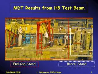
MDT Results from H8 Test Beam End-Cap Stand Barrel Stand L. Pontecorvo INFN-Roma
Outline • Test Beam aims • Data taken and measurements performed • H8 2003 Set Up • Main results on: • System aspects • Long Term stability of the system • Single tube resolution efficiency and calibration and variation with relevant parameters • Tracking in Barrel and End Cap • Efficiency and Sagitta resolution • Use of RPC in tracking to supply second coordinate • Test of Alignment system. • Combined Test Beam with Tile Cal & SCT. • X5 test beam and ageing test L. Pontecorvo INFN-Roma
Test Beam aims • Integration of trigger chambers (RPCs and TGCs) in the Muon System • Test of the trigger electronics with the 25 ns bunched beam • Test the absolute alignment • Tracking studies with ATLAS tracking code in the ATHENA • Large scale test of the final MDT electronics. • System Test • Complete gas studies • Test the DAQ-1 with the new MDT RPC and TGC read-out • Integration of the different muon software components (alignment, DCS, tracking, databases, etc.). • Complete the GEANT4 validation studies L. Pontecorvo INFN-Roma
Data taken and Measurements L. Pontecorvo INFN-Roma
The 2003 H8 Test Beam • Large-scale system test in the H8 beam line at CERN • Barrel: one tower with 6 MDT chambers equipped with RPCs in the middle and outer station (trigger and second coordinate) and optical alignment system • End-Cap: one sector with 6 MDT chambers and TGCs 1 triplet and two doublets (trigger and second coordinate) and optical alignment system 6 mt 6 mt 14 mt Barrel tower EC sector L. Pontecorvo INFN-Roma
MDT Electronics • 3720 channels readout with ATLAS FE electronics (1% of ATLAS): • Signal and HV Hedgehogs: final boards (155 Signal and 155 HV) • Mezzanines (ASD and ATM-3): final boards (155) • Chamber Service Module: CSM1 prototype boards (12) • Off-chamber: Muon Read Out Driver: 2 MRODs prototypes used to readout the 12 MDT chambers First time such a large MDT system operated First time that the full chain “mezzanine-CSM-MROD” successfully working But... It took about 1 month to debug the MRODs, despite a precommissioning phase had been done in NIKHEF before the Test After this period the MDT read-out worked smoothly for more than 2 months Next year: Test of the new CSM-2 with JTAG communication capabilities L. Pontecorvo INFN-Roma
Electronics Performances • Barrel electronics performance • End Cap electronics performance • 1800 channels in total • 13 dead channels 0.7% • 5 very noisy channels • 5 barely efficient 75 Mezzanines in total No dead Mezzanines • 1920 channels in total • 22 dead channels 1% • 1 very noisy channel • 1 barely efficient • 80 Mezzanines in total • 1 dead Mezzanine These few problems have been investigated and we understood their main sources L. Pontecorvo INFN-Roma
Channels die and resurrect during the run Drift Spectrum Event Number Electronic problem sources Solder bridge on a Signal HH • Most of the dead channels are due to the signal HH card: missing resistors, bad solders etc. • New procedure for the chamber commissioning including the use of a newly developed MECCA card • Discovered a problem when using the AMT chip in pair mode for charge measurement • Short pulses cause hang on AMT event matching circuit • A solution could be to perform the pairing in the CSM or in the MROD • This could heavily impact on the CSM/MROD design L. Pontecorvo INFN-Roma
RPC OFF RPC ON 40 Chambers out of beam 60 Hz Chambers in the beam Hz Noise and RPC-MDT interferences • Test of the MDT-RPC interference: • No additional noise is seen on the MDT when RPC are operated • Partial test of the new LV scheme (2 chambers supplied by the same LV channel) to be completed during 2004 TB. • Relative difference between single chamber cabling scheme and new cabling scheme: • < 10% difference RUN All H8 chambers Noise level 100 Hz Fake hit probability <10-4 Relative noise difference L. Pontecorvo INFN-Roma
Total drif t time vs Time (h) BML2 ML1 1 2 3 Long term stability • Long term stability: 12 MDT chambers kept under ATLAS-like gas flow and HV conditions for 3 months. • Total drift time constant within 1 ns during the full H8 data taking • Threefold serial gas connection produce a difference in the total drift time of few ns per tube in the series. • In the ATLAS working condition this effect will be smaller and will have no impact on the spectrometer performances 655 645 L. Pontecorvo INFN-Roma
200mm Rejected hits = d electrons Average 3s efficiency 97% 50mm Resolution vs drift distance Resolution & Efficiency Resolution improvement via Slewing Corrections • The resolution close to the wire is larger than 200 mm • In 2003 we could use the charge measurement to enhance by 40 mm position resolution via slewing corrections • The average tracking efficiency at 3 s is 97% • The decrease of the efficiency moving away from the wire is due to d electrons that produce a smaller drift distance L. Pontecorvo INFN-Roma
RT Relation & systematics Spectrum Integration • For optimal performances @ High Pt the Calibration of the chambers (RT-relation) has to be known with highest accuracy (< 20 mm on the whole drift distance) • RT relation should be determined only by the information of the chamber itself ( 1 ML): Autocalibration • The small number of measured points used in the autocalibration procedure imply the necessity of a rather large angular spread of the tracks used in the calibration procedure. First Iteration R-T Rel. Track Fitting Stop when residual flat and constant after n iterations (<10). Get R-T correction from residuals and iterate fit L. Pontecorvo INFN-Roma
H8 Data GARFIELD CO2 % (6.5-8) Calibration systematics • In H8 we studied the variations of the RT-relation as a function of the gas mixture with different percentages of CO2 • We find good agreement between the GARFIELD predictions and our measurements • This measurements are useful to design the gas system for the ATLAS experiment L. Pontecorvo INFN-Roma
DT=2.5 K RT(T1)-RT(T2) Garfield Measurement DT=3.5 K RT(T1)-RT(T2) Calibration systematic (2) • Temperature effect on RT relation DT=2.5 K Total drift time variation: 6.2 ns ~ 60 m DT=3.5 K Total drift time variation: 8.7 ns ~ 90 m Temperature effects can be parametrized and corrected L. Pontecorvo INFN-Roma
Effect of Air & H2O contamination • To analyze data with air and water contamination we need to calibrate the chambers but no angular scan is available • Develop a new method of calibration using all the barrel chambers to directly measure the RT-relation and the resolution of the chambers with air contamination. • Work in progress L. Pontecorvo INFN-Roma
GLOBAL TRACK LOCAL SEGMENTS Tracking in Barrel and End-Cap Tracks have been measured using the Barrel and End Cap chambers. 2 Photons sources of 7 mCi each have been used to produce a photon background of about 10 KHz per tube on some chambers Event Display PERSINT Local segment efficiency no photons (4/6 hits) : >99% Local segment efficiency with photon bck (4/6 hits): 95% preliminary L. Pontecorvo INFN-Roma
Outer Medium Inner Sagitta resolution • The sagitta is defined as the distance between the track defined by the external superpoints and the middle superpoint. • The resolution on this quantity directly gives the momentum resolution of the spectrometer • 2nd coordinate from RPC needed to correct for relative angles between wires to reach wanted precision • H8 gives the unique possibility to measure it in realistic conditions with a twofold aim: • Check the understanding of all the contributions to the sagitta resolution: calibration data (t0, drift-to-time relation), single-tube resolution, chamber geometry, description of passive material • Check the GEANT4 simulation: multiple scattering and intrinsic resolution • Check ATLAS reconstruction programs (eg. MOORE and MUONBOY in the ATHENA framework) L. Pontecorvo INFN-Roma
sag [cm] sag [cm] Hodo 10x10 trigger k = 9.8 +/- 0.3 [m/cm] k = 10.2 +/- 0.4 [m/cm] x pos of strip [cm] x pos of strip [cm] Sagitta Resolution: Use of RPC for 2nd coordinate The mean value of the measured sagitta depends on the 2nd coordinate measured by the RPC because of chambers angular misalignment in the wire plane. Large effects are seen mainly in the end cap with large area triggers (Hodo 60*100 cm2) but also with the 10*10 cm2 trigger the effect is sizable and has to be corrected END Cap L. Pontecorvo INFN-Roma
Sagitta resolution 140 GeV Barrel after corrections Measured sagitta width in Barrel : Estimated M.S. contribution @ 140 GeV: Estimated instrumental: We need to better understand the instrumental and the MS contribution to the sagitta resolution We will measure the sagitta resolution as a function of the momentum during the 2004 run. End Cap L. Pontecorvo INFN-Roma
Tracking from MDT to RPC Measure the relative cluster size population on RPC as a function of the MDT extrapolated track impact point. The Cluster size=2 events are concentrated close to the separation of 2 strips (green events), while for the large part of the strip the cluster size is 1 (gray events). Very few events show CS>2 (blue and red) RPC LVL1 trigger efficiency (25 ns run)Determined using Moore reconstruction vs trigger hits in the RPC L. Pontecorvo INFN-Roma
Alignment BIL shift along the Precision coordinate mm • In 2003 the relative alignment concept in the barrel has been validated more thoroughly than in 2002. • The BIL & BML chambers have been shifted and rotated of large amounts about all relevant angles: more than 80 movements have been measured. Sag from tracking Sag. after aligment corrections RMS=9 mm Sag from align mm • In 2004 we would like to test the absolute • alignment concept with even larger movements. BIL shift mm L. Pontecorvo INFN-Roma
Aligment (2): Angles BOL/BIL relative angles without alignment BOL/BIL relative angles after alignment Residual RMS =23 mrad L. Pontecorvo INFN-Roma
muons Pions/electrons Combined Test Beam • Online software developed in ALTAS framework(DAQ-1) • ATHENA based software integrated for the first time in onlineEvent Filter Data Flowin 2003 • Muon reconstruction program (Moore) used to flag muons during combined runs • Offline version used running on farm with 13 CPUs in parallel: EF latency~0.1 s • Seeding from LVL1and LVL2 foreseen in2004 • MDT number of hits in BIL2vsTilecal energy The Combined test beam in 2004 will integrate a full ATLAS slice from pixel to muons It will be the only real test of the commissioning and integration of the full ATLAS L. Pontecorvo INFN-Roma
40 cm ADC counts/MIP Distance from gas inlet Reference wire X5: Ageing Test • 137Cs [740 GBq] 660 KeV gsource + 100 GeV m beam • Allow achievement of g rates up to 10 times ATLAS (in EI MDT region)~1kHz/cm2 Ageing test with recirculating gas system: BIS chamber • 1 multilayer equipped with “ATLAS” circulating gas system (2 volumes per day with 10% fresh gas) • Other multilayer kept in flushing mode for comparison (2 volume per day) ~ 190 mC/cm Ageing effect observed close to gas inlet for tubes in recirculating gas system No effect observed in “flushed” ML L. Pontecorvo INFN-Roma
Evidence of Silicon pollution Whiskers made of Si and O (and possible H) clear evidence for a Si contamination as major ingredient for the observed ageing In spite of careful selection of the “circulating” gas system components used in the test few Si-contaminated components found with Hexane extraction + Infrared spectroscopy L. Pontecorvo INFN-Roma
Border effect: 2 additional points in the first/last 2 cm Eg=17, 22, 60 keV pedestal -40% 5 cm 5 cm Q=70 mC/cm Q=0 mC/cm X5: New Ageing Test • 6½ days/week of irradiation with 137Cs GIF/X5 source • ½ day of reference runs with 241Am sources • Gain variations measured by looking at 60 keV peak position A few tubes (3 out of 48) show largegain reduction in a small region (~5cm) close to the gas input: different effect from 2003 ? Effect not understood: more integrated charge needed L. Pontecorvo INFN-Roma
Conclusions: Some important achievements • Procedure and developed tools for the installation of the barrel (MDT+RPC) and end-cap (MDT) chambers tested • Large scale test of MDT electronics: systematic study over more than 3200 channels readout for 3 months • Long term stability: 12 MDT chambers kept under ATLAS-like gas flow and HV conditions for 3 months • Temperatures, gas parameters, RPC LV and HV, … Test of the “relative” concept of barrel and end-cap alignment systems • Preliminary studies on barrel and end-cap sagitta resolution with ATLAS offline software • TGC trigger electronics validated with 25ns bunched-beam • LVL1 muon trigger tested up to Central Trigger Processor prototype (with TGC trigger signals) and LVL1 latency measured • Test of the ATLAS online software including DAQ-1 and Event Filter • Prototype of Detector Control System tested for: alignment data, • Track reconstruction with ATHENA software using MDT and RPC (and TGC) raw data • First prototype of “conditions database” tested in alignment analyses • First ATLAS combined run with MDT, RPC, Tilecal and SCT performed L. Pontecorvo INFN-Roma
1 ML calibration (blue) 2MLs Calibration (pink) RT(20o) –RT(10o) RT(20o) –RT(7.5o) RT(20o) –RT(5o) Calibration systematics • A study of the Autocalibration systematics as a function of the angular spread of the tracks has been performed: • For tracks impinging on the chambers at 90o a minimal spread of 10o is needed for the required accuracy on the RT-Relation • Calibrationg with 2 MLs requires significantly less angular spread • We are trying to develop new calibration algorithms to minimize this figure. L. Pontecorvo INFN-Roma