Download
1 / 42
590 likes | 1.25k Vues
Introduction to MRI Principles. Hardware Contrast: T1 e T2 (T2*) weighting Localization: phase coding and k-space Localization: volume limiting, slice selection. Struttura e funzione: dall’avvento dell’imaging diagnostico …. Paul Lauterbur, MRI 1973. Godfrey N. Hounsfield, CT 1969.

E N D
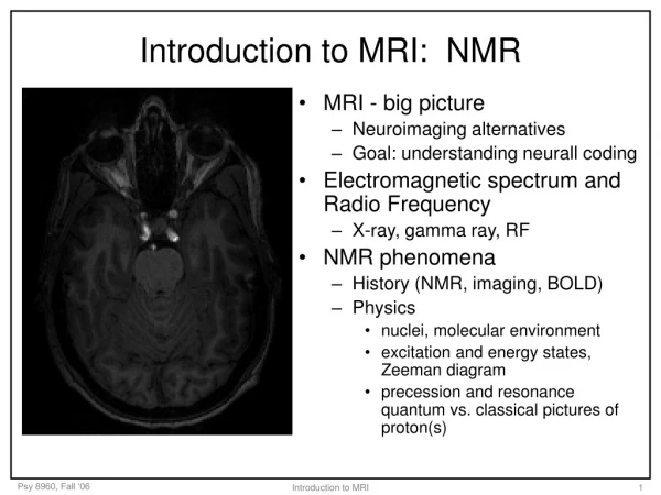
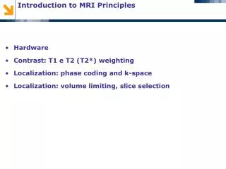
Introduction to MRI Principles • Hardware • Contrast: T1 e T2 (T2*) weighting • Localization: phase coding and k-space • Localization: volume limiting, slice selection
Struttura e funzione: dall’avvento dell’imaging diagnostico … • Paul Lauterbur, MRI 1973 • Godfrey N. Hounsfield, CT 1969 • Peter Mansfield, MRI
B1 63 MHz • G = | Gx,Gy,Gz| • B0 1.5T Hardware - Scheme of an MRI scanner(insets: main applications)
Hardware Overview The magnet produces the Bo field for the imaging procedure. The gradient coils for producing a gradient in Bo in the X, Y, and Z directions. • The RF coil produces the B1 magnetic field necessary to rotate the spins by 90o, 180o, or any other value selected by the pulse sequence. The RF coil also detects the signal from the spins within the body. • The shield prevents the high power RF pulses from radiating out through the laboratory. It also prevents the various RF signals from television and radio stations from being detected by the scanner.
Hardware Overview The heart of the imager is the computer. It controls all components on the imager. The RF components under control of the computer are the radio frequency source and pulse programmer. The source produces a sine wave of the desired frequency. The Pulse programmer shapes the RF pulses into apodizedsinc pulses. The RF amplifier increases the pulses power from milli Watts to kilo Watts. The computer also controls the gradient pulse programmer which sets the shape and amplitude of each of the three gradient fields. The gradient amplifier increases the power of the gradient pulses to a level sufficient to drive the gradient coils.
Preclinical system • Up to 11.7 T • Clinical system • 0.5 – 3 T • NMR spectrometer • Up to 17.5 T
Magnet • The main characteristics of a magnet are: • Type (superconducting or resistive electromagnets, permanent magnets) closed, tunnel-type MRI or open MRI. • Strength of the field produced, measured in Tesla (T). In current clinical practice, this varies from 0.2 to 3.0 T. In research, magnets with strengths of 7 T or even 11 T and over are used. • Homogeneity = • Its primary function is to generate a strong uniform static field (B0) for polarization of nuclear spins in an object. • Resistive magnets low field (< 0.15 T) • Permanent magnets up to 0.3 T • Superconducting magnets over than 11 T • The Earth’s magnetic field is approximately equal to 0.5 G • 1T = 104 G
Superconducting Magnet • The most commonly used magnets are superconducting electromagnets. These consist of a coil that has been made superconductive by helium liquid cooling. A superconducting magnet is an electromagnet made of superconducting wire. Superconducting wire has a resistance approximately equal to zero when it is cooled to a temperature close to absolute zero (-273.15o C or 0 K) by immersing it in liquid helium. Once current is caused to flow in the coil it will continue to flow as long as the coil is kept at liquid helium temperatures • Old generation • New generation
Superconducting Magnet • The length of superconducting wire in the magnet is typically several miles. The coil of wire is kept at a temperature of 4.2K by immersing it in liquid helium. • The typical volume of liquid Helium in an MRI magnet is 1700 liters • In the event of loss of superconductivity, electrical energy is dissipated as heat. This heating causes a rapid boiling-off of the liquid Helium which is transformed into a very high volume of gaseous Helium (quench). In order to prevent thermal burns and asphyxia, superconducting magnets have safety systems: gas evacuation pipes, monitoring of the percentage of oxygen and temperature inside the MRI room, door opening outwards (overpressure inside the room). • Superconducting magnets function continuously. To limit magnet installation constraints, the device has a shielding system that is either passive (metallic) or active (an outer superconducting coil whose field opposes that of the inner coil) to reduce the stray field strength.
Helmoltz Coils for open magnet • Magnet bore creates sever problems: claustrophobia, very limited access to patient. Open magnet scanners can be constructed by separating the main coil into an Helmoltz pair. Main applications are in surgery. • Consider two identical circular loop of radius a, separated by a distance d, and carrying the same current I in the same direction. • magnetic field of loop pair = sum of the two single loop fields. • Bz is uniform around z=0 when the distance is chosen to be the same as the radius of the loops. • This configuration has the ability to generate a uniform field in the vicinity of its midpoint
Helmholtz Coils (field uniformity) • d = a • d< a • d > a • a = 20 cm • a = 25 cm • a = 15 cm
Shim Coils • To obtain the most homogeneous magnetic field, the magnet must be finely tuned (“shimming”), either passively, using movable pieces of metal, or actively, using small electromagnetic coils distributed within the magnet. • The purpose of shim coils on a spectrometer is to correct minor spatial inhomogeneities in the Bo magnetic field. These inhomogeneities could be caused by the magnet design, materials in the probe, variations in the thickness of the sample, sample permeability, and ferromagnetic materials around the magnet. A shim coil is designed to create a small magnetic field which will oppose and cancel out an inhomogeneity in the Bo magnetic field.
Gradient Coils • They produce a linear variation in magnetic field intensity in a direction in space. This variation in magnetic field intensity is added to the main magnetic field, which is far more powerful. The variation is produced by pairs of coils, placed in each spatial direction. • This modifies resonance frequency, in proportion to the intensity of the magnetic field to which they are submitted (in accordance with Larmor’s equation: the stronger the field, the faster they precess). This variation in Larmor frequency also causes a variation and dispersion of spin phases. • IMPORTANT: the linearly varying field added by gradients is in the z direction, that of B0. Keep in mind that gradient direction (which can be any, by combining x, y, z gradients) refers to field “changes”, not to field direction. • Gradient characteristics • Gradient performances are linked to: • their maximal amplitude (magnetic field variation in mT/m), which determines maximal spatial resolution (slice thickness and field of view) • their slew rate, corresponding to their switching speed: high slew rates and low rise time are required to switch gradients quickly and allow ultra-fast imaging sequences such as echo planar (EPI) • their linearity, which must be as perfect as possible within the scanning area.
Gradient Coils • Assuming the standard magnetic resonance coordinate system, a gradient in Bo in the Z direction is achieved with a Maxwell type of coil. Current in the two coils flow in opposite directions creating a magnetic field gradient between the two coils. The B field at one coil adds to the Bo field while the B field at the center of the other coil subtracts from the Bo field.
Maxwell Coils for z-Gracdient • If the currents in the two loops are in opposite directions, the magnetic field along the z-axis is then • When the distance is chosen to be • times of the radius of the loops, • Bz around z=0 is linear along z.
Helmholtz Coil • Maxwell Coil
Transverse (x & y) Gradient Coils • The X and Y gradients in the Bo field are created by a pair of coils (Golay Coils). The X axis coils create a gradient in Bo in the X direction due to the direction of the current through the coils. The Y axis coils provides a similar gradient in Bo along the Y axis.
RF Coils • RF coils create the B1 field which rotates the net magnetization in a pulse sequence. They also detect the transverse magnetization as it precesses in the XY plane. • RF coils can be divided into three general categories: • 1) transmit and receivecoils (transceiver) • 2) receive only coils and • 3) transmit only coils. • An imaging coil must resonate, or efficiently store energy, at the Larmor frequency. All imaging coils are composed of an inductor, or inductive elements, and a set of capacitive elements. The resonant frequency, ν, of an RF coil is determined by the inductance (L) and capacitance (C) of the inductor capacitor circuit. • There are many types of imaging coils: • Volume coils surround the imaged object • Surface coils are placed adjacent to the imaged object. • An internal coil is one designed to record information from regions outside of the coil, such as a catheter coil designed to be inserted into a blood vessel.
RF Surface Coils • Surface coils are very popular because they have a good signal-to-noise ratio for tissues adjacent to the coil. In general, the sensitivity of a surface coil drops off as the distance from the coil increases.Here is an example of an image of the lower human spine obtained with a surface coil.
RF Volume Coils • Radio frequency coil that surrounds either the whole body, or one specific region, such as the head or a knee. Volume coils have a better RF homogeneity than surface coils, which extends over a large area. The most commonly used design is a (birdcage) bird cage coil.
Alderman-Grant Coil • Phased array coils
RF Coils – Surface vs. Volume Surface Coil vs. Volume coil • FOV • SENSITIVITY • SNR
RF Coils • In accordance with Kirchoff law, we obtain • The current is given by • If R=0 • From which it is obvious that I→Inf when • This phenomenon is called resonance and is called the resonant frequency
Tuning and matching • Variations in the size and tissue composition of the anatomy placed in an imaging coil affect the amount of RF energy getting into and the amount of signal detected from the imaged anatomy. • Tuning the probe entails adjusting two types of capacitors on the RF probe • The matching capacitor matches the impedance of the coil with imaged object to that of the 50 Ohm cable coming from the spectrometer. • The tuning capacitor changes the resonance frequency of the RF coil.
Magnetic resonance – physical principles • In classical mechanics, spin I can be represented with a rotation of the nucleus around an internal axis. • A rotating charge produces a magnetic moment m =I where is the gyromagnetic ratio of the nucleus. The modulus is: • where h=Planck constant • Nuclei can be considered as magnetic dipoles.
Magnetic resonance – physical principles • Magnetic moments corresponding to 1H take a pointing up (parallel to B0) or a pointing down (antiparallel to B0) orientation. • The number of parallel magnetic moments is larger than the number of antiparallel magnetic moments . • The magnetic moment orientation inside the plane orthogonal to B0 (transverse plane) remains random. • The result is a global magnetizationM0 along B0 (longitudinal magnetization).
Magnetic resonance – physical principles • The external magnetic field B0, trying to align the magnetic moment m along the direction of B0, produces a torque C=m X B0 • Rate of change of angular moment vector: • Motion equation: • The result is that the magnetic moment m precesses around B0 keeping a constant angle.
Magnetic resonance – physical principles • The same condition subsists when a spinning gyroscope precesses under the effect of gravity.
Magnetic resonance – physical principles • The precession frequency is proportional to the external magnetic field intensity: • f = 1/2π · g · B0Larmor frequency • For 1H, if B0=1T: • f=42.57 MHz (radiofrequency) • Precession angular velocity: • W= g · B0 The gyromagnetic ratio g is a characteristic of the nucleus and represents the ratio between the magnetic moment and the angular moment.
Spin up/down precession • Static bulk magnetization MZ = M0 no signal • RF pulse rotating transverse • magnetization Mxy • z • f. Larmor • M0 • y’ • Precession at • f0 = 63 MHzLarmor freq. • B1 63 MHz • B0 1.5T • Mxy • x’ • 63 MHz • Mxy NMR signal at RF • spin-spin interaction: • RF signal decay T2 • spin-lattice interaction • MZ saturation recovery T1 • z • z • y’ • z • MZ <M0 • Mxy • y’ • y’ • x’ • 63 MHz • x’ • x’ • 63 MHz • 63 MHz Nuclear magnetic resonance and signal
Weights in a spin-echo sequence • T2 weighting • Mxy • Mxy • M0 • protondensity • T1 • T2 • T2A = T2B • T2B • T2A • t • TE • t • 100 ms • 100 ms • T1 weight in the • ripetition • Mz • M0 • T1A • Mz Mxy • T1B • saturation • TR • TR • t • 100 ms T1 and T2 contrast weight
Example T1 image for GM, WM, liquor segmentation • T1-3D, voxel 1x1x1 mm3, healthy subject, age 24. (Siemens Magnetom Avanto 1.5T). Contrast of GM, WM,liquor. • Courtesy IRCCS S. Maria Nascente, Fondazione Don C.Gnocchi ONLUS, Milano
k = TPEf0 G / B0 • Gradient G LOCALIZATION: PHASE ENCODING AND K-SPACE1 – Gradient on develops phase shifts accumulate through time Tpe • fast • Gradientaxis r • B(r) = B0 + G·r • slow
k = TPEf0 G / B0 LOCALIZATION: PHASE ENCODING AND K-SPACE2 – cosine and sine are developed into the material • Vector k describes spatial frequncy valueand orientation
Acquisition of a Fourier Transform sampleat frequency corresponding to k value • amplitude of NMR at r • In-phase and quadrature demodulation samples amplitude and phase • amplitude and phase • Integration over all volume performed by antenna
Magnetic resonance imaging: slice selection • As shown previously, MRI is volumetric and 3D scans are actually used. • However, slice selection greatly reduces acquisition time by reducing reconstruction • problem from 3D to 2D. The 2D FT is the most frequent acquisition protocol. • A slice selection gradient (e.g, Gz) is switched on during excitation pulse. • All the protons positioned in zp have Larmor precession frequency Wzp=g(B0+Gzzp) • An RF pulse with frequency Wzp excites only nuclei with coordinate z=zp.
Magnetic resonance imaging: slice selectionany direction can be obtained
2D FT spin echo sequence • Spin Echo • Slice selection • Phase endcoding – moves to raw ky • Phase endcoding • Frequency endcoding • Frequency endcoding – gradient x during acquisition • causes progressive movement in kx direction • (note, frequency encoding is used as progressive phase encoding)