Download

1 / 72
1.01k likes | 2.44k Vues
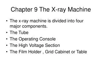
Chapter 9 The X-ray Machine. The x-ray machine is divided into four major components. The Tube The Operating Console The High Voltage Section The Film Holder , Grid Cabinet or Table. Chiropractic X-ray Room. Floor mounted x-ray tube stand. Wall grid cabinet or Bucky

E N D
Chapter 9 The X-ray Machine • The x-ray machine is divided into four major components. • The Tube • The Operating Console • The High Voltage Section • The Film Holder , Grid Cabinet or Table
Chiropractic X-ray Room • Floor mounted x-ray tube stand. • Wall grid cabinet or Bucky • Mobile Table with grid cabinet (optional) • Non-Bucky Film Holder (optional)
Chiropractic X-ray Room • Control Booth should contain the operator console and technique charts and space to store cassettes. • The wall between the booth and X-ray unit is shielded.
Chiropractic X-ray Room • High Voltage Section or Generator used to change incoming power to levels needed to produce x-rays.
The X-Ray Tube Development • Dr. Roentgen used a Crookes-Hittorf tube to make the first x-ray image. • There was no shielding so x-rays were emitted in all directions.
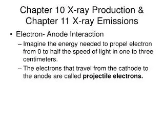
The X-Ray Tube Development • The Coolidge Hot cathode tube was a major advancement in tube Design. The radiator at the end of the anode cool the anode.
The X-Ray Tube Development • This is the variety of tube designs available in 1948. • The Coolidge tube was still available.
The X-Ray Tube Development • Two major hazards plagued early radiography. • Excessive radiation exposure • Electric Shock
The X-Ray Tube Development • This is a modern rotating anode x-ray tube. It is encased completely in a metal protective housing.
The X-Ray Modern X-ray Tube • There are two principle parts: • The rotating anode • The cathode • Any tube that has two electrodes is called a diode.
The X-Ray Modern X-ray Tube • There are two principle parts: • The rotating anode • The cathode • Any tube that has two electrodes is called a diode.
Protective Housing • The tube is housed in a lead lines metal protective housing. • The x-ray photons are generated isotropically or in all directions. • The housing is designed to limit the beam to window.
Protective Housing • The tube can not have more than 100 mR at 1 m (26 µ C/kg) / Hour when operated at it maximum output.
Protective Housing • The housing also provide mechanical support and protection from damage. • On some tubes, the housing also contains oil that provides more insulation and a thermal cushion.
Protective Housing • Never hold the tube during an exposure. • Never use the cables or terminals as handles.
Protective Housing • The housing incorporates specially designed high voltage receptacles to protect against electrical shock. • Some housing have a fan for cooling.
The X-Ray Tube Glass Envelope • The glass envelope is made of Pyrex to withstand the tremendous heat produced during x-ray. • The window is a 5 cm square with a thin section of glass where the useful beam is emitted.
The Cathode • The cathode is the negative side of the tube and contains two primary parts: • The filaments • The focusing cup
The Filaments • Most tube have two filaments which provide a choice of quick exposures or high resolution. • The filaments are made of thoriated tungsten.
The Filaments • Tungsten is used in x-ray tube because of it’s high melting point of 3410°C. • X-rays are produced by thermionic emission when a 4 A or higher current is applied.
Focusing Cup • The focusing cup has a negative charge so that it can condense the electron beam to a small area of the anode.
Filament Current • When the x-ray machine is turned on, a low current flows through the the filament to warm it and prepare it for the big thermal jolt necessary for x-ray production.
Filament Current • The filament is not hot enough for thermionic emission. Once the current is high enough for thermionic emission a small rise in filament current will result in a large rise in tube current.
Filament Current & Tube Current • The x-ray tube current is adjusted by controlling the filament current. • The relationship between tube and filament current is dependent upon the tube voltage.
Space Charge • When emitted by the filament, the electrons form a cloud near the filament momentarily before being accelerated to the anode. This is called a space charge.
Saturation Current • When very high mA and very low kVp, the thermionic emission can be space charge limited. • With high mA the cloud makes it difficult for subsequent electrons to be emitted. • Above 1000 mA space charge limited exposure can be a major problem.
The Anode • The anode is the positive side of the tube. • X-ray tubes are classified by the type of anode: • Stationary ( top) • Rotating (bottom)
The Stationary Anode • Stationary anodes are used in dental x-ray and some portable x-ray machine where high tube current and power are not required.
The Rotating Anode • The rotating anode allows the electron beam to interact with a much larger target area. • The heat is not confined to a small area.
The Rotating Anode • The anode serves three functions: • Receives the electrons emitted from the cathode. • It is a electrical conductor. • Mechanical support for the target.
The Rotating Anode • The Anode must also be a good thermal conductor. • When the electron beam strikes the anode more than 99% of the kinetic energy is converted to heat.
The Rotating Anode • Tungsten-rhenium is used as the target for the electron beam. • Tungsten is used for three reasons • High atomic number • Heat conductivity • High melting point..
The Rotating Anode • The rotor is an electromagnetic induction motor. • It spins at 3400 rpm. • High speed anodes spin at 10,000 rpm.
The Rotating Anode • Even with the anode rotating, some melting occurs. The heat must be rapidly dissipated. • Molybdenum and copper are used to rapidly transfer the heat from the target.
The Rotating Anode • When the exposure button is depressed, current is applied to the tube that produces a magnetic field that starts the rotation of the anode.
The Rotating Anode • When the anode is spinning at the correct speed, the exposure can be made. • After the exposure is completed, it slows by reversing the motor.
Tube cooling • The x-ray tube uses all three forms of cooling. • Radiation • Conduction • Convection
Focal Tracks • With a rotating anode, the electrons strike a moving target forming focal tracks on the tube.
Line-Focus Principle • The focal spot is the area of the anode from which the x-rays are emitted. • The focal spot impacts the geometric resolution of the x-ray image.
Line-Focus Principle • By angling the anode target, one makes the the effective focal spot much smaller than the actual area of interaction. • The angling of the target is know as the line focus principle.
Line-Focus Principle • The Effective Focal Spot is the beam projected onto the patient. • As the anode angle decreases, the effective focal spot decreases. • Diagnostic tube target angles range from 5 to 15°.
Line-Focus Principle • The advantage of Line focus is it provides the sharpness of the small focal spot with the heat capacity of the large large focal spot.
Line-Focus Principle • Smaller target angles will produce smaller effective focal spots and sharper images. • To cover a 17” the angle must be 12° • To cover 36” the angle must be 14°
Off Focal Radiation • Remember that x-rays are produced in all directions. The electrons can rebound and interact with other areas of the anode. • This is called Off-Focal Radiation.
Control of Off Focal Radiation • A diaphragm is placed between the tube and the collimator to reduce off focus rays.
Anode Heel Effect • One unfortunate consequence of the line-focus principle is that the radiation intensity on the cathode side of the x-ray tube is higher than the anode side.
Anode Heel Effect • The x-rays are emitted isotropically or in all directions. • Some of the beam is absorbed by the target resulting in a lower intensity.
Anode Heel Effect • The difference in the intensity can vary by as much as 45%. • If the center is 100% the anode side of the beam can as low as 75% and the cathode as much as 120%.
Anode Heel Effect • The heel effect should be considered when positioning areas of the body with different thickness or density. • The cathode side should be over the area of greatest density.