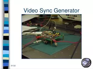
Video Sync Generator
Video Sync Generator. 01/33. Video Sync Generator. ECE 345 design project: Spring 2000 Prof. Swenson T.A. : Jon Benson Group # 54: Cyrus K. Ashrafi ashrafi@uiuc.edu Mike barber m-barber@uiuc.edu Ryan Berube rberube@uiuc.edu. 02/33. The Video Sync: Objective. Suppressed Sync.

Video Sync Generator
E N D
Presentation Transcript
Video Sync Generator 01/33
Video Sync Generator • ECE 345 design project: Spring 2000 • Prof. Swenson • T.A. : Jon Benson • Group # 54: • Cyrus K. Ashrafi • ashrafi@uiuc.edu • Mike barber • m-barber@uiuc.edu • Ryan Berube • rberube@uiuc.edu 02/33
The Video Sync: Objective Suppressed Sync Recaptured Signal • Impress Sync on Signal 03/33
The Video Sync: Objective • SSAVI Sync-Suppressed Signal 04/33
The Video Sync: Objective • Blanking Level • Peak White Level • Synchronizing Level • Difference Between Black • and Blanking Levels • Peak-to-Peak Value of • Color Burst • Peak Level, Including • Chrominance Level • Line Blanking Interval • Interval Between Time • Datum and Backedge of Line- • Blanking Pulse • Front Porch • Synchronizing Pulse • Build-Up Time of the Line- • Blanking Pulse • Build-Up Time of the Line- • Synchronizing Pulse • Start of Sub-Carrier Burst • Duration of Sub-Carrier • Burst • Line Synchronizing Signal • (non-sync suppressed) 05/33
The Video Sync: Objective • NTSC Video Sync 06/33
The Video Sync: Circuit • Top Copper Layer 07/33
The Video Sync: Circuit • Assembly Top 08/33
The Video Sync: Circuit • Overall Circuit 09/33
The Video Sync: Circuit • Power and Serial Communications 10/33
The Video Sync: Circuit • Video Signal Processing 11/33
The Video Sync: Circuit • Microprocessor Controller 12/33
The Sync Generator:After Negative Regulator and Pi Filter 19/33
Problems • Video Signal Must Be Pure • VHS VCR’s Impose Their Own Automatic Gain Control (in order to make the varied voltage level of the signal equivalent) • Test Pattern is Needed (in order to check exactly how the signal is modified when it is encoded) • Video Oscilloscope • Good Sampling Rate and Frame Synchronization • Location of the Main Frame Sync • A Good Starting Point is Critical to the Functionality of the Descrambling Circuit 31/33
Recommendations • Once the Main Frame Sync Point is Found • Replace the Microprocessor with CMOS Digital Logic Circuit (though less flexible, faster) 32/33
Video Sync Generator 33/33