Download
1 / 24
260 likes | 290 Vues
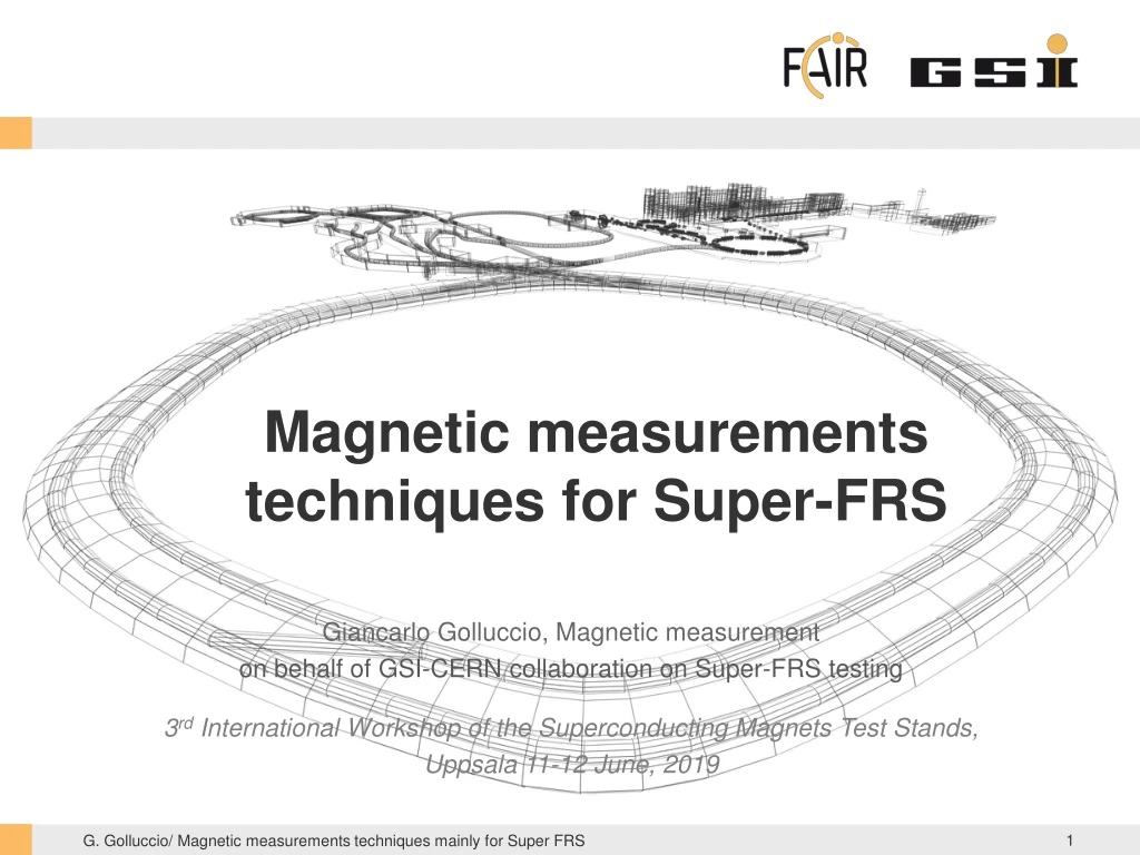
Magnetic measurements techniques for Super-FRS. Giancarlo Golluccio, Magnetic measurement on behalf of GSI-CERN collaboration on Super-FRS testing 3 rd International Workshop of the Superconducting Magnets Test Stands, Uppsala 11-12 June, 2019. Outline. Magnets Overview

E N D
Magnetic measurements techniques for Super-FRS Giancarlo Golluccio, Magnetic measurement on behalf of GSI-CERN collaboration on Super-FRS testing 3rd International Workshop of the Superconducting Magnets Test Stands, Uppsala 11-12 June, 2019
Outline • Magnets Overview • Super-FRS superconducting magnets • Short/Long multiplet design parameters • Dipoles design parameters • Magnetic measurements • Magnetic measurement campaign • Measurement devices • Measurement strategy • Devices • SSW • Rotating coils • Translating fluxmeter • 3D mapper
Super-FRS superconductingmagnets 32 Multiplets: ASG, Italy Magnets Long quadrupole Short quadrupole Sextupole Octupole Steerer Dipoles: Elytt, Spain 18 × 9.75° bending magnet 3 × 11° bending magnet 3 × 9.75° bending branch magnet 7000mm 6500mm 2600 mm 6000mm
Short/Long multiplet design parameters • Short multiplets composed by: a Quad (plus octupole coils for some of them) and an hexapole (at left or right side of the quad) Steerer dipoles or hexapoles
Magneticmeasurementcampaign • Conformity to QA SAT parameters • Magnet to magnet reproducibility • Localization of the magnetic field for installation purposes (fiducialization) • Requires: reproducible Integral field measurements • Local field information (field roll off) • the 3D magnetic field model can be tuned on the measurements • only for first of series • Provide a feedback during operation in control room • Requires: dedicated measurement campaign for sensors calibration • Not planned yet for super-FRS • Measurement in the 2D region and integral • Only for the first of series • Verify mechanical assembly tolerances • Requires: local measurements and sensitivity to field errors
Magneticmeasurementcampaign • Magnetic measurement for the Super-FRS • Requirements from GSI to CERN in the 2014 • Based on that, CERN started the development of four new measurement systems • Challenges: • Large dimension of the Good Field Region • 190 mm radius for quadrupoles • 380 x 140 mm for dipoles • Extended fringe field • No possibility of standard calibration procedures • Requirements of accuracy and fiducialization
4 measurement devices 3D Hall sensor Translating fluxmeter Rotating coil Single stretched wire (SSW) Vibrating wire (VW)
Measurement strategy • The integral field and field quality of each FOS is measured with two independent systems/methods • Dipoles: Translating fluxmeter, Stretched Wire (Vibrating Wire) • Multipoles: Rotating coils, Stretched Wire (Vibrating Wire) • Extended program for FOS • For dipoles (FOS 9.75°, 11° and each branch dipole): additional local map with a 3D hall probe mapper ( 3m length, top, mid, bottom of GFR boundaries and three current levels) • For multipoles (quadrupole and sextupole): local field and field harmonics provided with an 100 mm length rotating coil, 100 mm step size over 2.6 m (for long quad) • An extended measurement plan for the pre-series is needed for guarantee redundancy and flexibility for the series testing phase • Standard program for the Series • Only integral measurements • use of only Stretched Wire measurement is preferable. • In case of not acceptable divergences w.r.t. FOS measurements, alternative fluxmeter (for dipole) or rotating coil (for multiplet) will be used. • The magnetic measurement program at cold for the series is 10 days, however, as function of the results of the first of series this schedule can be adjusted
Measurement strategy • Pre-series • enough time for study and cross-checking both global and local field distribution and homogeneity • Series • Checking magnet to magnet reproducibility • No contingency for tracing manufacturing errors and corrective actions for the magnet is foreseen, for the moment. • Under responsible of the magnet work packages, additional measurements might be discussed and can be arranged.
Measurement devices The standard uncertainty of an instrument is a function of the operating conditions (field range/frequency, gradient, temperature etc. … ) that is the way can only be estimated in situ. Testing time and effort are needed to estimate and improve... • Repeat to get rid of random errors • Flip and repeat to estimate systematic effects • either the magnet or the instrument • Inverse polarity(if possible) to remove intrinsic or environmental offsets • e.g. residual field and earth field • Redundancy • Cross-calibrate measurement systems • Covering of all measurement scenarios • Cross-check measurement results • Results confidence • Flexibility Accuracy vs testing time
Measurement device: SSW Stretched wire for multiplets and dipoles Stages with 400 mm stroke equipped with vibrating wire sensors:Ready for operation
Measurement device: SSW Wire moved in two steps of width xinside a quadrupole of unknown gradient GCoordinate frame offset from magnetic axis by unknown amount x0Flux integrated over the wire length Lw Uncertainty depends on the flux measurement and displacements increasing too much x get too close to the poles, harmonicerrors perturb the result: Measuring the Flux integrated at several angular positions along the GFR allows also to measure the multipoles (polygons)
Measurement device: VW XY micrometric stages XY long range stages • Stretched-wire system with AC current passed through the wire Lorentz force oscillation BdL • zero amplitude = wire on magnetic axis • integrated harmonics by stepwise scan around a circle • Tuning of the wire detectors required to operate in the linear range wire XY optical wire position detectors
Measurement devices: Rotating coil Rotating coils for multiplets 2.6 m rotating coil shaft with 350 mm diameter • Carbon Fibre structure • Support structure for PCB • rigidity • Weight reduction • 3 PCBs • 2 x 1.326 m length • 1 x 0.1 m length • 5 Radial coils • 72 turns 6 layers • External radius 167 mm
Measurement devices: Rotating coil Fourier component of the flux [T @ rref ] Coil area Coil rotation radius 2D ideal rectangular rotating coil geometry integration constant: lost with fixed coil measurements,irrelevant (unphysical) for rotating coils integration boundsset by precise angular encoder rotation speed fluctuationshave negligible effects measured flux depends on both the fieldand coil geometry [units @ rref] Normalized (from absolute) absolute Area and radius need to be calibrated…
Measurement devices: Rotating coil Rotational radius calibration: Not possible with standard procedures: Average radius calibration will be done in situ calibration with SSW crosscheck with mechanical measurements (metrology and laser tracker)
Measurement devices: Rotating coil Coil bucking for improving sensitivity to higher order harmonics: A-B-C+D Remove dipole and quadrupole component A-3B+3C+D Remove dipole, quad and sextupole component (the factor 3 can be obtained using the inner layer of the pcbs) A E D B C Total surface 1.40203 m2 Two layers 0.46736m2 Deviation from design values in 10-4
Measurement devices: Translating fluxmeter 4 m measurement length translating fluxmeter for dipoles • Aluminium structure • Guiding system • Non magnetic linear encoder (5 um resolution MicroE MII6000) • PCB plate with • 13 coils of 0.6 m2 • 1D Hall probe for offset adjustment 5 m Aluminium encoder scale tape
Measurement devices: Translating fluxmeter An array of coils translating along z Voltage output: field at the point nΔz:
Measurement devices: Translating fluxmeter Measurement from a prototype system: 102 mm coil 10 mm coil NMR 102 mm coil 10 mm coil NMR
Measurement device: 3D mapper 3D mapper for dipole 3D with 3000 x 1000 x 1000 mm stroke mapper and 3D hall probe sensor Hall probe with on board amplifiers (25 gain) and thermal regulation
Measurement device: 3D mapper On going: Calibration of 3D sensors: orthogonality, linearity, planar effects Optimization of control loop Vibration and dumping of the measuring arm for on-fly measurements Software for stage control and data acquisition