Download
1 / 14
140 likes | 168 Vues
Investigate radiation scatter during C-arm procedures to determine optimal radiographer positioning for minimal exposure. Study involved dosimeters placed at various heights and distances, showcasing non-uniform scatter cloud pattern. Results confirm the hypothesis and emphasize the importance of knowing high-exposure areas for staff safety.

E N D
C15 Scatter Cloud of the C-arm
Objective • Investigate the radiation scatter during C-arm fluoroscopic examinations • Determine the best location for the radiographer to stand to achieve the lowest dose of radiation while performing radiographic procedures
Hypothesis • Radiation scatter cloud is non-uniformly distributed • Scatter radiation would be higher under the examination table
“Scatter Cloud” • Quantifiable and reproducible radiation is created during fluoroscopic procedures • The outcome data resembles a “scatter cloud” • Room set up and imaging technique variables influence scatter radiation levels • Risk • Radiation doses can vary widely • Although radiation exposure is a necessary risk, protection of staff and patients require a clear understanding of how the exposure radiates • The risk cannot be eliminated entirely
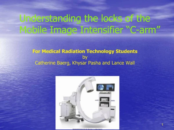
Method • Digital imaging of an acrylic adult abdominal CT phantom was exposed at both anteroposterior and lateral projections
Method • Dosimeters were positioned at different heights and distances • Height from the floor: 2 feet, 3 feet, 4 feet, and 5 feet • Distance from isocenter: 3 feet and 6 feet
Materials • OEC 9900 Elite C-arm • Acrylic Adult Abdominal CT Phantom • RaySafe™ i2 Dosimeters (4) and Software • IV Pole • Lead Aprons • Tape
Dosimeter • RaySafe™ i2 dosomiters visualize X-ray exposure in real-time and displays exposure values • Provides instant feedback to permit radiology staff to adjust their behavior to reduce unnecessary radiation exposure • Measurements are simultaneously stored for analysis for furthering new behaviors and allowing comparisons over time
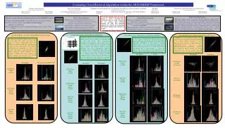
The scatter cloud was most intense at the 2 foot and 3 foot levels • The measured values at the 4 foot and 5 foot levels diminished to almost nothing • The greatest intensity of radiation was recorded at the tube end of the plane that passed through the tube and control portions of the C-Arm Graph of C-Arm Scatter Cloud in AP Position Data *Due to physical limitations, measurements could not be taken at the 3-foot distance at the control end or the 5-foot distance at the image intensifier end in this orientation.
Graph of C-Arm Scatter Cloud in Lateral Position Data • The dose rate of the scatter cloud was most intense at the 2 foot and 3 foot levels • The measured values at the 4 foot and 5 foot levels diminished to almost nothing • The greatest intensity was to the left and right of the emitter at a distance of 3 feet away *Room constraints prevented the placement of sensors at the 6-foot point on the tube end. The values for this position have been set to zero for graphing purposes.
Discussion • The results of our measurements appear to support the hypothesis that the scatter cloud produced by the C-Arm is non-uniform • The intensity of the dose rate diminished greatly from the 6 foot to the 3 foot mark • As anticipated based on the inverse square law
Discussion • Dose rate was reduced greatly past the 3 foot height mark • perhaps due to the construction of the C-Arm and the phantom used. • Dose rate was particularly high near the tube end in the lateral orientation • The non-uniform nature of the scatter cloud is important • Knowledge of the areas of greater dose rate can help radiation workers determine where to position themselves while the C-Arm is being used
Conclusion • Our data and research indicates the best place for the radiographer to stand is behind the control end of the C-arm
Resources • Haqqani, O. P., Agarwal, P. K., Halin, N. M., & Iafrati, M. D. (2013). Defining the radiation “scatter cloud” in the interventional suite. Journal of Vascular Surgery, 58(5), 1339-1345. doi:10.1016/j.jvs.2013.01.025 • Kim, K. P., & Miller, D. L. (2009, February). Minimising radiation exposure to physicians performing fluoroscopically guided cardiac catheterisation procedures: A review. Retrieved March 07, 2019, from https://www.ncbi.nlm.nih.gov/pmc/articles/PMC2902901/ • Manchikanti, L., Cash, K. A., Moss, T. L., Rivera, J., & Pampati, V. (2003, August 06). Risk of whole body radiation exposure and protective measures in fluoroscopically guided interventional techniques: A prospective evaluation. Retrieved March 07, 2019, from https://www.ncbi.nlm.nih.gov/pmc/articles/PMC194671/ • Mitchell, F. P. (n.d.). Prevention of radiation injury from medical imaging ... Retrieved March 07, 2019, from https://www.jvascsurg.org/article/S0741-5214(10)01731-3/fulltext • Software Used: • AutoCAD 2019 (Version P.46.0.0) [Computer software]. (n.d.). Retrieved March 22, 2019, from https://www.autodesk.com/products/autocad/overview • EZGIF Animated GIF editor and GIF maker. (n.d.). Retrieved March 22, 2019, from https://ezgif.com/ • Plot.ly. (n.d.). Retrieved March 22, 2019, from https://plot.ly/ Online Graphing Application