Processor Design
Processor Design. CT101 – Computing Systems. Content. GPR processor – non pipeline implementation Pipeline GPR processor – pipeline implementation Performance Issues in pipeline. GPR Example processor (1). Consider a simple GPR architecture 32 GPR registers, R0 to R31

Processor Design
E N D
Presentation Transcript
Processor Design CT101 – Computing Systems
Content • GPR processor – non pipeline implementation • Pipeline • GPR processor – pipeline implementation • Performance Issues in pipeline
GPR Example processor (1) • Consider a simple GPR architecture • 32 GPR registers, R0 to R31 • Value of R0 is always 0 • Data types: • 8 bit bytes, 16 bit half words and 32 bit words (integer data) • Operations work on 32 bit integers • 8 bit and 16 bit operands are loaded into the 32 bit registers with sign bit duplicated • Addressing modes: • Immediate (16 bit field) • Displacement mode (contents of register added to 16 bit address field)
GPR Example Processor (2) • Examples of I Instructions • LW R2, 50 (R3) – Regs[R2] <- Mem{50 + Regs[R3]} • LW R2, 50 (R0) – Regs[R2] <- Mem{50 + 0} • SW R3, 500 (R4) – Mem{500+Regs[R4]}<-Regs[R3] • BNEZ R4, name – if (Regs[R4]){PC<-name} • JR R3 – PC<- Regs[R3] (jump register) • JALR R2 – Regs[R31] <-PC+4; PC<-Regs[R2] (jump and link register)
GPR Example Processor (3) • Example of R – type instructions • ADD R1, R2, R3 – Regs[R1]<- Regs[R2]+Regs[R3] • SLT R1, R2, R3 – if (Regs[R2]<Regs[R3]{Regs[R1]<-1}else{Regs[R1]<-0} (set if less than)
GPR example processor (4) • J name – PC<-name • JAL name – Regs[31]<-PC+4; PC<-name (jump and link)
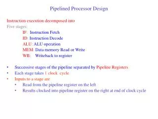
Example processor implementation • Instruction Fetch Cycle (IF): • IR Mem[PC] • NPC PC+4 • Instruction Decode/Register Fetch Cycle (ID) • A Regs[IR6…10] • B Regs[IR11…15] • Imm ((IR16)16##IR16…31 • Instruction Execution/Effective Address Cycle (EX) • Memory Reference Instruction • ALUOutput A + Imm • Register – Register ALU Instruction • ALUOutput A func B • Instruction Execution/Effective Address Cycle (EX) • Register – Immediate ALU Instruction • ALUOutput A op Imm • Branch Instruction • ALUOutputNPC + Imm • Cond (A op 0) • Memory Access/Branch Completion Cycle (MEM) • Memory Reference - Load • LMD Mem[ALUOutput] • Memory Reference - Store • Mem [ALUOutput] B • Branch Instruction • If (cond) {PCALUOutput} else {PCNPC} • Write-Back Cycle (WB) • Register – Register ALU Instruction • Regs[IR16…20] ALUOutput • Register –Immediate ALU Instruction • Regs[IR11…15] ALUOutput • Load Instruction • Regs[IR11..15] LMD
Instruction Fetch • Instruction Fetch Cycle (IF): • IR Mem[PC] • NPC PC+4 • Operation: • send out the PC and fetch the instruction from memory • Increment the PC by 4 to address the next instruction and save it in NPC (Next Program Counter) register
Instruction Decode • Instruction Decode/Register Fetch Cycle (ID) • A Regs[IR6…10] • B Regs[IR11…15] • Imm ((IR16)16##IR16…31 • Operation • Decode the instruction and access the register files to access the registers; the output of the general purpose registers are read into two temporary register (A and B) for use in latter clock cycles; fixed field decoding is involved. • The lower 16 bits of IR are also sign extended and stored into temporary register Imm, for latter use
Instruction Execution • Instruction Execution/Effective Address Cycle (EX) • Memory Reference Instruction • ALUOutput A + Imm • The ALU adds the operands to form the effective address and places the result into the register ALUOutput • Register – Register ALU Instruction • ALUOutput A func B • The ALU performs the function specified by the instruction and places the result into the ALUOutput register • Register – Immediate ALU Instruction • ALUOutput A op Imm • The ALU performs the operation indicated by the opcode on the value from register A and the value from Imm. Result is placed in ALUOutput register • Branch Instruction • ALUOutput NPC + Imm • Cond (A op 0) • The ALU adds the contents of NPC with the sign extended value of Imm to compute the address of the branch target. Register A is checked to see if the branch is taken. The comparison operation op is determined by the branch opcode (i.e. op is “==“ for instruction BEQZ)
Instruction Memory Access • Memory Access/Branch Completion Cycle (MEM) • Memory Reference Instruction • Load • LMD Mem[ALUOutput] • Store • Mem [ALUOutput] B • Access memory if needed. • If instruction is a load, then data returns from memory and is placed in LMD register (Load Memory Data) • If instruction is a store, then the data from B register is written back into the memory, at location stored in previous cycle in ALUOutput • Branch Instruction • If (cond) {PCALUOutput} else {PCNPC} • If the instruction branches, then the PC is replaced with branch destination address. Otherwise it is replaced with incremented PC in the register NPC
Instruction Write-Back • Write-Back Cycle (WB) • Register – Register ALU Instruction • Regs[IR16…20] ALUOutput • Register –Immediate ALU Instruction • Regs[IR11…15] ALUOutput • Load Instruction • Regs[IR11..15] LMD • Write the results back into the register file, whether the data comes from the main memory or as a result of an operation (from ALU); the register destination can be in two positions up to the instruction type
Pipeline • Pipelining is an implementation technique whereby multiple instructions are overlapped in execution • The goal of the pipeline is to reduce the execution time for a set of instructions • Today, pipelining is the key implementation technique for modern processors • Each stage in the pipeline completes a part of the instruction • Throughput is determined by how often an instruction exits the pipeline (gets completed)
Basic Pipeline (1) • We can pipeline the presented datapath with no changes by starting a new instruction on each clock cycle • While each instruction will take 5 clock cycles to complete, each clock cycle, the hardware will initiate the execution of a new instruction
Basic Pipeline (2) • Example processor datapath, drawn in pipeline fashion
Basic Pipeline (3) • The use of pipeline forces us to think about: • Datapath should use separate instructions and data memories • The memory system must deliver five times the bandwidth • The register file is used in two stages: for reading in ID stage and for writing in WB stage • This means that we need to be able to perform two reads and a write every clock cycle • What if a read and a write target the same register? • PC – to start a new instruction every clock, PC has to be incremented and stored every clock and this should be done during IF in preparation for next instruction • The problem occurs when we consider the effect of taken branches, that change the PC as well, but not until the MEM stage • We will deal with this problem by reorganizing the way PC gets written
Basic Pipeline (4) • Pipelining the datapath requires that values passed from one pipe stage to the next pipe stage must be placed in registers. Those registers, placed between each pipe stage, are called PIPELINE REGISTERS. • The pipeline registers serve to convey data and control information from one stage to the next. • PC (Program Counter) can also be thought as a pipeline register that sits before the IF phase of an instruction, leading to one pipeline register for each stage. • Most of the data flows from left to right, which is from earlier in time to latter in time. The paths that flow from right to left which carry the PC and the values for WB stage) introduce complications into our pipeline.
Basic Pipeline (5) • Pipeline version for our example processor datapath • The datapath is pipelined by adding a set of registers, one between each pair of pipe stages • Instruction Fetch • IF/ID.IR mem[PC] • IF/ID.NPC, PC If (EX/MEM.cond) {EX/MEM.ALUOutput}else{PC+4} • Instruction Decode Cycle/Register Fetch • ID/EX.A Regs[IR6…10]; ID/EX.B Regs[IR11…15] • ID/EX.NPC IF/EX.NPC; • ID/EX.IR IF/EX.IR • ID/EX.Imm (IF/ID.IR16)16##IF/ID.IR16…31 • Instruction Execution/Effective Address Cycle (EX) • ALU Instruction • Register – Register ALU Instruction • EX/MEM.IR ID/EX.IR • EX/MEM.ALUOutput ID/EX.A func ID/EX.B • EX/Mem.Cond 0 • Register – Immediate ALU Instruction • EX/MEM.IR ID/EX.IR • EX/Mem.ALUOutput ID/EX.A op ID/EX.Imm • EX/Mem.Cond 0 • Instruction Execution/Effective Address Cycle (EX) • Memory Reference Instruction • EX/MEM.IR ID/EX.IR • EX/MEM.ALUOutput ID/EX.A + ID/EX.Imm • EX/MEM.Cond 0 • EX/MEM.B ID/EX.B • Instruction Execution/Effective Address Cycle (EX) • Branch Instruction • EX/MEM.ALUOutputID/EX.NPC + ID/EX.Imm • EX/MEM.Cond (ID/EX.A op 0) • Memory Access (MEM) • Memory Reference Instruction • MEM/WB.IR EX/MEM.IR • For Load • MEM/WB.LMD Mem[EX/MEM.ALUOutput] • For Store • Mem [EX/MEM.ALUOutput] EX/MEM.B • Memory Access (MEM) • ALU Instruction • MEM/WB.IR EX/MEM.IR • MEM/WB.ALUOutput EX/MEMALUOutput • Write-Back Cycle (WB) • ALU Instructions • For Register – Register ALU Instruction • Regs[MEM/WB.IR16…20] MEM/WB.ALUOutput • For Register –Immediate ALU Instruction • Regs[MEM/WB.IR11…15] MEM/WB.ALUOutput • Memory Access (Load) Instruction • Regs[MEM/WB.IR11..15] MEM/WB.LMD
Pipelined Instruction Fetch • Instruction Fetch • IF/ID.IR mem[PC] • IF/ID.NPC, PC If (EX/MEM.cond) {EX/MEM.ALUOutput}else{PC+4} • Operation: • send out the PC and fetch the instruction from memory • Increment the PC by 4 to address the next instruction or save the address generated by a taken branch of a previous instruction in execution stage
Pipelined Instruction Decode • Instruction Decode Cycle/Register Fetch • ID/EX.A Regs[IR6…10]; ID/EX.B Regs[IR11…15] • ID/EX.NPC IF/EX.NPC; • ID/EX.IR IF/EX.IR • ID/EX.Imm (IF/ID.IR16)16##IF/ID.IR16…31 • Operation • Decode the instruction and access the register files to access the registers; the output of the general purpose registers are read into two temporary register (A and B, part of the pipeline registers ID/EX stage) for use in latter clock cycles • The lower 16 bits of IR, stored in pipeline registers from IF/ID stage are also sign extended and stored into temporary register Imm (part of ID/EX pipeline registers), for latter use • Values for NPC and IR are passed to the next stage of pipeline registers (from IF/ID to ID/EX)
Pipelined Instruction Execution (1) • Instruction Execution/Effective Address Cycle (EX) • Memory Reference Instruction • EX/MEM.IR ID/EX.IR • EX/MEM.ALUOutput ID/EX.A + ID/EX.Imm • EX/MEM.Cond 0 • EX/MEM.B ID/EX.B • The value of the IR from previous stage of pipeline registers (from ID/EX) is passed onto the next stage of pipeline registers (to EX/MEM) • ALU adds the operands (stored in the previous stage pipeline registers – ID/EX to form the effective address and places the result into the register EX/MEM.ALUOutput, part of the next stage pipeline registers. • The Cond register (of EX/MEM pipeline registers) is set to 0 (no branch) • The value of B register from previous stage (ID/EX) is saved into the next stage pipeline registers (EX/MEM) for usage in next cycle (contains the value to be saved by a store operation).
Pipelined Instruction Execution (2) • Instruction Execution/Effective Address Cycle (EX) • ALU Instruction • Register – Register ALU Instruction • EX/MEM.IR ID/EX.IR • EX/MEM.ALUOutput ID/EX.A func ID/EX.B • EX/Mem.Cond 0 • The ALU performs the function specified by the instruction and places the result into the ALUOutput register (of the next stage pipeline registers) • Register – Immediate ALU Instruction • EX/MEM.IR ID/EX.IR • EX/Mem.ALUOutput ID/EX.A op ID/EX.Imm • EX/Mem.Cond 0 • The ALU performs the operation indicated by the opcode on the value from register A and the value from Imm (both retreived from ID/EX pipeline registers). Result is placed in ALUOutput register of the EX/MEM pipeline registers
Pipelined Instruction Execution (3) • Instruction Execution/Effective Address Cycle (EX) • Branch Instruction • EX/MEM.ALUOutput ID/EX.NPC + ID/EX.Imm • EX/MEM.Cond (ID/EX.A op 0) • The ALU adds the contents of NPC with the sign extended value of Imm to compute the address of the branch target. Register A is checked (from the pipeline registers of ID/EX stage) to see if the branch is taken. The comparison operation op is determined by the branch opcode (i.e. op is “==“ for instruction BEQZ)
Pipelined Instruction Memory Access (1) • Memory Access (MEM) • Memory Reference Instruction • MEM/WB.IR EX/MEM.IR • For Load • MEM/WB.LMD Mem[EX/MEM.ALUOutput] • For Store • Mem [EX/MEM.ALUOutput] EX/MEM.B • Access memory: • If instruction is a load, then data returns from memory and is placed in LMD register (Load Memory Data) of MEM/WB pipeline registers • If instruction is a store, then the data from B register of EX/MEM pipeline registers is written back into the memory, at location stored in previous cycle in ALUOutput (of EX/MEM pipeline registers)
Pipelined Instruction Memory Access (2) • Memory Access (MEM) • ALU Instruction • MEM/WB.IR EX/MEM.IR • MEM/WB.ALUOutput EX/MEMALUOutput • Save the contents of the ALU output to the next stage pipeline registers, for usage in WB stage. • Propagate the contents of IR to the next stage, for usage in the next clock cycle
Pipelined Instruction Write-Back • Write-Back Cycle (WB) • ALU Instructions • For Register – Register ALU Instruction • Regs[MEM/WB.IR16…20] MEM/WB.ALUOutput • For Register –Immediate ALU Instruction • Regs[MEM/WB.IR11…15] MEM/WB.ALUOutput • Memory Access (Load) Instruction • Regs[MEM/WB.IR11..15] MEM/WB.LMD • Write the results back into the register file, whether the data comes from the main memory or as a result of an operation (from ALU); the register destination can be in two positions up to the instruction type
Control Path for Pipeline Processor • Pipeline version for our example processor datapath • The datapath is pipelined by adding a set of registers, one between each pair of pipe stages To control this simple pipelined datapath, we just need to determine how to set the control for the four multiplexers in the datapath. The two multiplexers in the ALU stage are set depending on the instruction type, which is dictated by the IR filed of the ID/EX register. The top ALU input multiplexer is set by whether the instruction is a branch or not and the bottom multiplexer is set by whether the instruction is a register-register ALU operation or any other type of operation. The multiplexer in the IF stage chooses whether to use the current PC or the value of EX/MEM.ALUOutput (the branch target) as the instruction addresses. This multiplexer is controlled by the field EX/MEM.Cond. The forth multiplexer is controlled by whether the instruction in WB stage is a load or an ALU operation.
Performance Issues in Pipeline (1) • Pipelining increases the processor throughput • Number of instructions completed per unit of time • Pipelining does NOT increase the execution speed of individual instruction • In fact, it actually decreases the execution speed per individual instruction, due to the overhead introduced in the data path and control of pipeline • The increase in the throughput means that a program runs faster and has lower total execution time, even if no single instruction runs faster
Performance Issues in Pipeline (2) • There are limits on the physical limit on the pipeline, caused by: • Execution time of each instruction doesn’t decrease • Imbalance between pipeline stages • Reduces performance, since the clock can not run any faster than the time needed for the slowest pipeline stage • Pipeline overhead • Arises from the combination of pipeline register delay and clock skew
Performance Computation (1) • Consider our example un-pipelined processor • The ALU operations and branches uses four cycles. The relative frequency of ALU operations is 40% and 20% for branches • The memory operations use five cycles. The relative frequency is 40 % • Clock cycle is 10ns • Consider a 1ns overhead to the clock introduced by the pipeline • How much speedup in the instruction execution rate will we gain from pipeline?
Performance Computation (2) • The average instruction execution time for the un-pipelined machine is: • Clock Cycle * Average CPI (Clock cycles Per Instruction) = 10 ns * [(40% + 20 %) * 4 + 40 % * 5] = 10 ns * 4.4 = 44 ns • In pipeline implementation, the clock must run at the speed of the lowest pipeline segment plus the clock overhead, which would be 11ns
References • “Computer Architecture – A Quantitative Approach”, John L Hennessy & David A Patterson, ISBN 1-55860-329-8 • “Computer Architecture”, Nicholas Charter, ISBN – 0-07-136207