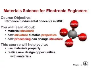
ELECTRONIC MATERIALS
ELECTRONIC MATERIALS. Soochow University 2009. In Profile - Huang. More than 30 years: electrochemistry research and surface chemistry (Sep. 1975) Near 30 years: WA Near 30 years: AESF More than 20 years (from July 1986) : CSIS And others. Contents. Introduction Wire & Cable

ELECTRONIC MATERIALS
E N D
Presentation Transcript
ELECTRONIC MATERIALS Soochow University 2009
In Profile - Huang More than 30 years: electrochemistry research and surface chemistry (Sep. 1975) Near 30 years: WA Near 30 years: AESF More than 20 years (from July 1986): CSIS And others
Contents • Introduction • Wire & Cable • Semiconductor • Capacitor • PCB • MEMS • Battery • CD-R • EMI/RFI • ITO • Electrowetting, LCD &LED
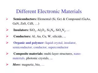
Electronic Materials Basic structures of solids a. electron orbitals b. energy bonds c. crystal structures: bcc, fcc…. d. crystal solids: bcc, -Fe V Cr Mo W fcc, -Fe Al Ni Cu Ag Pt Au hcp, -Ti Zn Zr metal oxides or nitrides…: ceramics
e. polycrystalline & noncrystalline solid polycrystalline: for example PVD amorphous solids: the atoms or ions are arranged randomly, hence there are dangling bonds (incomplete energy bonds) and voids. In general, stable only up to a certain temp. polymers: partially crystalline and partially amorphous f. phase diagrams
g. Techniques for crystal growth & thin-film deposition: Czochralski growth of semiconductorh. crystal imperfections: defect and impurityi. diffusion in solids: depends on the size difference between the impurity and the host atoms (or ions) via vacancy or interstitial
Wire & Cable • WA: The Wire Association International • Ag: 1.49 -cm at 20oC • Cu: 1.72 -cm, OFHC 0.008%O2 • Cu alloy: TS (tensile strength) 1.2-1.4%Cd, 200% TS, 85-90% <10% Sn, P & Si, 3-400% TS, 40-50% 2-2.5% Be, Ag • Al: 99.3% purity 45% TS, 62% , 30% density Au:
Optical fiber • Core: fused mixtures of metal oxide 3 – 80 μ • Cladding material: low n 20 – 50 μ Total reflection at the cladding-core material.
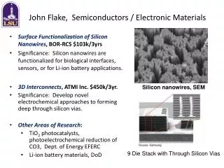
semiconductor • 1. physics classification of materials: insulator metal semiconductor: electron and hole conduction, the resistivity of silicon depends upon the number of acceptor or donor atoms added and the temperature
2. Wafer preparation a. sand: silicon dioxide containing less than 1 % impurities. b. react with carbon: SiO2 + C → Si(99% purity) + CO2 c. react with hydrogen chloride: Si + 3HCl → SiHCl3 + H2 d. decomposed using electric current: SiHCl3 + H2→ Si(ultrapure polycrystalline) + 3HCl e. Silicon crystal growth: Czochralski method
CZ method • Si at 1415oC in a rotating quartz crucible →Add the desired impurities →An arm with a piece of seed crystal with the Si →Ar is used to prevent contamination of the molten Si →The seed crystal is slowly withdraw from the molten Si
CZ拉晶法 • CZ拉晶法:CZ (Czochralski) 法進行單結晶矽之生產;此方法目前被工業界廣泛地使用於大尺寸單結晶之製造。此法先將原子排列不規則之多結晶矽原料在高溫下熔化 (Meltdown) ,再以單結晶之晶種 (Seed) 慢慢浸入矽熔湯中,經過晶頸生長 (Neck Growth) 、晶冠生長 (Crown Growth) 、晶身生長(Body Growth) 、尾部生長(Tail Growth)等製程,即可得到與晶種相同之排列整齊之晶格、原子,成為製造矽晶圓所需要之單結晶材料。
wafer • Orientation: XRD provides the orientation • sawing: thin slices (wafer) • Polishing: one side is mirror-like finish
3. Epitaxial deposition • Is the deposition of a single crystal layer on a substrate (same composition). Etchant (HCl gas) is used to create nucleation site for epitaxial deposition Method of epitaxial deposition: sputtering, evaporation: low rate vapor growth: deposited from SiCl4 and SiH4 (better from hydrogen reduction SiCl4(g) + H2(g) = Si + HCl(g) or pyrolysis of SiH4(g) = Si + H2(g)
4. Oxidation • The ability to grow a chemically stable protective layer of SiO2 on Si, makes Si the most widely used semiconductor. • This protective layer is growth in atmospheres containing either oxygen or water vapor (faster) at temp. in the range of 900 – 1300oC.
5. Impurity introduction: by diffusion • A. predeposition: heat semiconductor to a temp. and an excess of the desired dopant is made available at the surface of the wafer. The dopant will enter the crystal lattice. Solid solubility. Ion implanation: take ions of a desired dopant, accelerates them using an electric field. • B. drive-in: is performed in a high temp. diffusion furnace.
6. Photomasking • For the successful transfer of an image to the surface of a wafer: generate a mask and transfer to the wafer through use of a photoresist (光阻). • The circuit be fabricated by sequentially transferring images the wafer while performing steps such as CVD, epitaxy, predeposition, and drive-in, or metallization between successive image transfers. • Light-hardened resist is negative resist, while light-softened resist is positive resist.
Basic photoresis flowchart • Surface preparation – application of resist – soft bake (low temp. cure to dry resist, expose, develop (dissolve the unpolymerized resist)) – visual inspection – hard bake (higher temp. cure to completely dry and polymerize) – etch – strip resist – visual inspection
7. Chemical vapor deposition • The formation of a stable compound on a heated substrate by the thermal reaction or decomposition of gaseous cpds. • SiH4 + heat = Si (polycrystalline)+ H2 • SiH4 + O2 = SiO2 + H2 • SiH4 + NH3 = Si3N4 (a dense dielectric used to passivate circuits) + H2
8. Metallization • After the devices in the silicon substrate have been fabricated, they must be connected together to perform circuit functions. • Vacuum deposition of Al by sputtering • Copper deposition
MEMS Microelectromechanical systems nm?