Module Flow
Module Flow. 11.1 Circuit Protection Overview 11.2 Circuit Protection Device Features and Options 11.3 Common Design Errors 11.4 Common Test Errors 11.5 eFuses 11.5a eFuse Overview 11.5b eFuse vs. Fuse 11.5c eFuse vs. Polyfuse. Circuit Protection Fundamentals.

Module Flow
E N D
Presentation Transcript
Module Flow • 11.1 Circuit Protection Overview • 11.2 Circuit Protection Device Features and Options • 11.3 Common Design Errors • 11.4 Common Test Errors • 11.5 eFuses • 11.5a eFuseOverview • 11.5b eFuse vs. Fuse • 11.5c eFuse vs. Polyfuse
Circuit Protection Fundamentals 11.1 Circuit Protection Overview
Circuit Protection – What is it ? • Many things with many names • Inrush Control • Hotswap • Hotplug • Current Limiting • Electronic Circuit Breaker • Short Circuit Protection • Soft Start • Over Voltage Protection (OVP) • eFuse • Load Power Limiting • FET SOA Limiting ( Protecting the Protector ! ) • Reverse Current Protection (ORing) • Often Required for Agency Rating • UL, CSA – North America • EN, IEC, (CENELEC) – Europe • CCC Mark (CNCA) - China ~ the same functions
Circuit Protection – What is it ? • Circuits designed specifically to…. • Prevent Fire ! --“Keep the smoke in!” • Keep small problems from growing big • Minimize damage by quickly isolating failures • Prevent potentially disruptive power bus disturbances • One small transient can take down/reset an entire system • What Gets Protected ? SUPPLY CONNECTORS LOAD POWER FET
Circuit Protection – Where Is It Used ? • Telecom Equipment • Datacenters / Servers • Storage / HDD, SSD, Midplanes • Industrial Control • 24 or 48 V typically • Tower Mounted Antennas • Merchant Power
Circuit Protection – The Basic Parts • Most Common Elements • Location.. • Sometimes on the Load Side of the Connector • Sometimes on the Supply Side of the Connector Element for modulating current Element for sensing current LOAD BOARD BACKPLANE Element for controlling the FET
Circuit Protection Fundamentals 11.2 Device Features and Options
“End customers can’t make you design in protection circuits but they can make you wish you had.” – Design review wisdom
Device Features/OptionsSome of the Choices • FET • Internal or External • Inrush control • dV/dT, or di/dT • Current Limit • Always, Never, or just at startup • Fault response • Latch off or Retry • Short Circuit Response • Latch Off or Retry • Control • I2C or Analog Control • Outputs • Power Good, Fault, FET Fault • ILIMIT Accuracy • 20% Standard, 10% Pretty Good, 5% Very Good • FET SOA protection.. Or not • Allows use of smaller FET and provides very high survivability • Current Indicator Output (IMON) • Analog or Digital Output ? • Digital Output requires internal ADC and typically includes PIV Monitoring • ORing Control • Linear or Hysteretic
Device Features/OptionsInternal FET vs. External FET Internal FET External FET • Highly Integrated • Few External Parts • Internal sense FET • Built it Power Limiting • Extremely well protected • Compromises are made • FET process vs. Analog process • FET package vs. Analog package • Require careful thermal design • Generally not found in app > 5 A • Flexible RDSON (Designers Choice) • More feature options • No limit on upper current limit • Generally more accurate • More external parts • RSENSE, FET • RS, CSfor configuration • Larger foot print
Device Features/Options FET SOA Protection • One of the least understood but most appreciated features • Allows use of smaller, less expensive FETs • Analog multiplier calculates PDIS_FET in real time and compares result to PROG pin • If PLOAD > PROG then gate drive reduced to lower ILOAD and PFET • TI is now the ONLY manufacturer to offer true Power Limiting !
Device Features/Options FET SOA Protection • Dynamically adjusts ILIMIT to be approximately proportional to 1/(VDS)2 • Limits PDIS of FET to programmed limit Orange = Violetx (VIN – Blue) PDIS= ILOAD x VDS PDIS VOUT ILOAD ILOAD VOUT TPS2420 Startup into 15 Ω, 700 μF TPS2420 Limits FET PDIS < 5 Watts
Device Features/Options Power Limiting – Startup into overload response • SOA protection keeps FET safe even when starting up into a severe overload • Fault timer limits T(ime) factor of SOA • Some competitive devices will reduce ILIMIT over a limited range and with limited protection. • ONLY TI has true FET SOA Power Limiting built into the Hotswap Controller !!! ILOAD VOUT CT PDIS TPS2420 Startup into overload
Typical Inrush/OCP Design Steps • Select RSENSE to set ILIMIT and IFASTTRIP • ILIMIT = VTH/RSENSE - VTH typically 25 – 50 mV • Simplest controllers have fixed VTH • High VTH → Better Accuracy but Higher I2R Losses • Fast trip – (Short Circuit) threshold usually 1.5x -3x ILIMIT Level • Select CFAULT to get desired TFAULT • Set TFAULT long enough to allow all downstream caps to charge (TCHARGE)before time out • TCHARGE ~ CV/I (C = Bulk Cap, V = VOUT, I= ILIMIT ) • Set TFAULT as short as reasonable to minimize FET stress during overcurrent events • Ensure that TFAULT x VIN X ILIMIT is within SOA curve • Select FET that can withstand TFAULT x VIN x ILIMIT x ~1.5 …..SOA !! • Set FET SOA Power Limit on devices so equipped • Design tools available for some devices - check webpage • TPS24700/10/20, TPS2490/1/2/3, TPS2480/1, LM5064/6/7/9, LM25061/6/9
Questions To Ask During Design • Will a load get plugged into a live socket? • Will a load get unplugged from a live socket? • Is it OK for supply to collapse if one load shorts? • Are multiple loads connected to a common supply? • OK for all loads to shut off if one load shorts? • Do loads need ability to ride through transients? • Do loads needs protection from voltage surges? • Do loads have large capacitance on the inputs? • Are multiple supplies powering the load or bus?
Circuit Protection Fundamentals 11.3 Common Design Errors
Common Design Errors • SOA of FET too Small • Layout Issues • Inadequate Transient Protection
SOA of FET Too Small • SOA = Safe Operating Area • SOA Chart – Every FET has one • Defines Bounds of FET Operation • VDS_MAX = Vertical Limit • ID_MAX = Horizontal Limit • RDSON limits ID at lower voltages • Theoretical PMAX = 3000 W • Fault Time Is Critical • Longer Fault time means bigger FET • Shorter Fault Time allows higher peak power • Most Stressful FET Events • Startup into short • Shorted load while under full load 103 102 101 100 10-1 10-2 ID_MAX RDSON 1 ms IDS Drain to Source Current 10 ms 100 ms 1 s DC 10-2 10-1 100 101 102 VDS Drain to Source Voltage VDS_MAX Putting FETs in parallel does NOT improve dynamic SOA !!!
SOA of FET Too SmallExample - 12 V, 50 A Server • Without Power Limiting • PMAX = ILIMIT x VSUPPLY = 600 W • TSOA_MAX = ~800 us • With Power Limiting • PMAX_LIMITED = 50 W • As VDS increases ILIMIT is reduced • TSOA_MAX = 10 ms • Smaller FET can be used • @ 50 A will start limiting when VDS> 1V • Common Error to Pick FET Too Small 103 102 101 100 10-1 10-2 50 A 1 ms 10 ms IDS Drain to Source Current 100 ms 1 s DC 10-2 10-1 100 101 102 VDS Drain to Source Voltage 12 V
Layout Issues - A Little Stray R Can Make a Big Error • Critical Kelvin Connections • Sense Runs • Critical Short Run • Ground • Gate • High Current Runs • Poor Kelvin Runs… • Inaccurate/variable ILIMIT • Poor High Current Runs • Voltage droop • Power loss • Overheating
Inadequate Transient Protection • All wires are inductive • Inductance stores energy • When the FET turns off, voltage spikes occur • Positive Spikes at Input to Switch/FET • Negative Spikes at Output of Switch/FET LOAD CURRENT LOAD VOLTAGE
Inadequate Transient Protection • To squelch inductive spikes from supply / load leads • Caps and/or TVS at UUT Input to clamp positive spike • Schottky Clamp across output to clamp negative spike • Short, Wide Leads and Runs
Circuit Protection Fundamentals 11.4 Common Test Errors
Common Test Error Sources • Current Probes • Electronic Loads • Transients From Long Supply Leads • Supply ILIMIT Too Low
Current ProbesCurrent Probe Behavior • ↑ Great For Observing Waveform Shapes • ↑ Don’t have to be “In The Loop”…Nice !! • Simply Clamps around feed or RTN wire • ↓ Need Frequent Degaussing/Cal • ↓ Not So Great for Precise Measurements • Limited Bandwidth • 1% Accuracy at Best
Current ProbesFor precise DC current measurements • If ILOAD < 10 Amps use Multimeter on Current Scale • If ILOAD > 10 Amps Use Shunt and Multimeter • Pick RSENSE so VRSENSE @ ILIMIT = 50-100 mV • Note….Now VOUT_SUPPLY ≠ VIN_LOAD...so measure VLOAD at The Load!
Electronic Loads • Good for DC Loading and Automated Tests • Proper Setup Very Important • Ex. - Constant Current, Constant Power, Constant Resistance • But…often Have Switch Transients When Stepping Load • Transients Can Cause Premature Trip When Measuring ILIMIT • So What Do We DO ??
Electronic LoadsFor Minimal Transients While Adjusting Load Method 1: Use Power Resistors as Loads Method 2: Use Power FET as Load • A bit tedious and Old School… but accurate • A collection of fixed and variable resistors is best • Apply “Last Half Amp” With Small Wire Rheostat • Can be effective with eLoads also • Connect FET and Series Resistor as Load • Adjust Potentiometer to vary Current • Make Sure the FET can Handle the power !!!!
Long Supply Leads • All wires are inductive • Long Supply Leads can have significant L • Lab Test Environment Usually Worse Than Final Application! • Reason for TVS and diodes on most TI EVMs • When the FET turns off, voltage spikes occur • To counter inductive spikes from supply / load leads • Caps and/or TVS at UUT Input to clamp positive spike • Schottky Clamp across output to clamp negative spike • Twisted Supply leads
Supply ILIMIT Too Low • Lab Supply Limit Sometimes Set Slightly Above ILIMIT_LOAD • VSUPPLY can sag due to I limiting during overload / short circuit testing • Sagging VSUPPLY can cause UV shutdown before ILOAD reaches IFASTTRIP • UV Shutdown is typically much slower than Fast trip (SC) Shutdown • Slow shut down can violate FET SOA, resulting in dead FETs • Fix 1: Ensure PS set to supply currents ABOVE fast trip level • Fix 2: Attach bulk caps at input of UUT before test is run
Trends in Circuit Protection • Accuracy • Current limit, power limit, monitoring • Efficiency • Low RDSON, low IQ • High levels of integration • i.e. bring FET, RSENSE into the package • I2C, PMBus for control and monitoring • Especially PMBus with Intel Grantley processors • eFuses replacing/augmenting fuses & polyfuses • High Power POE Systems (25-100 Watts)
Circuit Protection Fundamentals 11.5a eFuse Overview
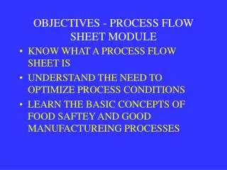
Integrated Circuit Protection TypesPower controlling element contained therein Initial $ Level of Protection 好运 Wishful Thinking Polyfuse (PTC) eFuse Fuse
What is an eFuse? An active circuit protection device that… • Will: • Limit current at inrush • Prevent load or source damage due to OC events • Have an internal FET to control the load current • Might: • Provide OVP (none, fixed, adjustable) • Have adjustable fault time and/or current limit • Have indicator outputs (Fault, PG, etc.) • Be able to control turn on slew rate • Have a load current indicator output • Be on source side of a connector or load side or.. • Be nowhere near a connector
Typical Applications for eFuse m-SATA SSD SAS HDD Enterprise Class SSD Set-Top Box DVD Player Internet TV Storage Server Chassis Appliances
Brand Damage – A Hidden CostIt’s not fair and that won’t change • Most end users don’t know or care how a product works • Even fewer know or care about circuit protection • A good fuse design in a bad system can still get the blame • Dirty power, poor transient control, can cause a fuse to blow • A load with a blown fuse is viewed as the problem…not the faulty source • Blame should go to the source of “bad” power...but rarely does • END CUSTOMER DOESN’T CARE about power specs !!! • Your board died….now fix it!!! • Replacement board likely to blow a fuse, too • Customer not happy – switches to competitive brand • Control your products’ destiny !! • Don’t rely on other systems to “do the right thing” • Protect the product, the brand, the profit, your career ! • Someone will pay….don’t let it be you!
Backend costs of “fuse only” designs • Tangible costs • Replacement of nonfunctional product • RMA admin costs / time • Shipping broken/new devices from/to customer • Truck rolls, service personnel • Intangible backend costs • Unhappy retailers • Brand damage • Loss of customer(s) • In the end, we all want happy customers • It’s that simple, it’s that complicated
Circuit Protection Fundamentals 11.5b eFuse vs. Fuse
Why Not Use a Fuse? • Slow • Inaccurate • Lossy • Leave a load unpowered after event
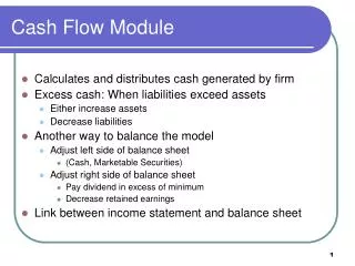
“Fast Blo Fuse” Trip Time vs. CurrenteFuse vs. Fuse eFuse trip range Fusible fuse trip range eFuse Limit ! Time (sec.) Time and trip limit inaccuracies mean bigger power supplies
Fuses Are Slow…Even the Fast Ones • eFuse Performance • ILIMIT is programmable, predictable, and stable over temp • Bus droop and supply stress reduced by tight over current tolerance
Fuses are Lossy • Higher resistance -> more energy -> more heat -> higher OPEX • 13x more power lost with fuse! • 800 mV/2A = 400 mΩvs. eFuse @ 30 m Ω • Lifetime cost of 1 Watt = $2 to $18 ( customer supplied numbers) • Includes energy cost, distribution infrastructure, HVAC, product life Little Fuse 231Series Lower Losses using TPS2590 ( 30 mW )
Fuses are Inaccurate • Fuse makers recommend the INOMINAL< 75% IFUSE_RATED • Power supplies must be overspec’d • Accommodate fuse derating, fuse tolerance, PFUSE • Bigger supplies = more CAPEX, more OPEX Seconds
Fuse’s Behavior is Sloppy and Stressful During Overload After Overload • Much slower than eFuse • No active current limiting • Uncontrolled turn off time • Bus droop likely • More stress on supplies & load • High I2R losses • 10x+ nom. trip current for 3 ms • No auto reset • Inoperative system • Module, fuse, or system must be replaced • Repair costs • Field returns • Unhappy Customers