Download
1 / 26
260 likes | 387 Vues
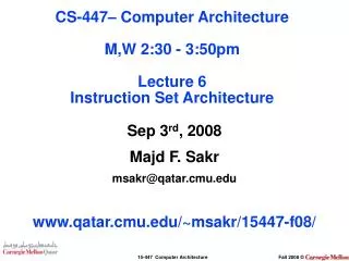
CS-447– Computer Architecture M,W 2-3:50pm Lecture 10 Datapath & Control. September 17th, 2008 Majd F. Sakr msakr@qatar.cmu.edu www.qatar.cmu.edu/~msakr/15447-f08/. Lecture Objectives. Learn what a datapath is, and how does it provide the required functions.

E N D
CS-447– Computer Architecture M,W 2-3:50pmLecture 10Datapath & Control September 17th, 2008 Majd F. Sakrmsakr@qatar.cmu.edu www.qatar.cmu.edu/~msakr/15447-f08/
Lecture Objectives • Learn what a datapath is, and how does it provide the required functions. • Appreciate why different implementation strategies affects the clock rate and CPI of a machine. • Understand how the ISA determines many aspects of the hardware implementation.
The Big Picture of a Computer System Main Memory Input /Output Processor Datapath Control
ALU Focusing on CPU & Memory CPU Memory Datapath PC Data IR Register File Control Unit Address
Destination Register File Source 1 Source 2 Control ALU Result The Datapath : (Register File) A load / store machine (RISC), register – register where access to memory is only done by load & store operations.
Register File Design control Reg B Reg A s1_bus s2_bus 4->1 MUX 4->1 MUX 4->1 MUX Reg C Reg D # Bits / Register = 8 => 8 MUXs # Registers = 4 => 4 to 1 each MUX
A0 A1 A2 A3 B0 B1 B2 B3 S0 S1 S2 S3 C0 C1 C2 C3 D0 D1 D2 D3 Register File: 4 registers, 4 bits / register A0B0C0D0 A0B0C0D0 MUX4 -> 1 MUX4 -> 1 A1B1C1D1 A1B1C1D1 MUX4 -> 1 MUX4 -> 1 A2B2C2D2 A2B2C2D2 MUX4 -> 1 MUX4 -> 1 A2B2C2D2 A2B2C2D2 MUX4 -> 1 MUX4 -> 1 s0 s1 s2 s3 Control bits Control bits
Destination Register File Source 1 Source 2 Control ALU Result The Datapath The Result of the operation performed in the ALU needs to be stored in a register.
Destination: 2 registers / 3-bits per register Result from ALU to Destination Bus DeMux1 DeMux2 DeMux3 Control Register 1 Register 2
Quiz • Draw your design of a register file: • Three registers, each is 2-bits wide • Two source buses, one destination bus • How many & what size: • Muxes did you use? • Demuxes did you use? • Total number of control lines?
Destination Register File Source 1 Source 2 Control ALU Result The Datapath : (ALU) A load / store machine (RISC), register – register where access to memory is only done by load & store operations.
Simple ALU Design s1_bus s2_bus control Add/Sub Shift/Logic 16 to 8 MUX dest_bus
ALU How about the Control? CPU Memory Datapath PC Data IR Register File Control Unit Address
Control Logic The Control Unit
A simple device Build a custom controller for a vending machine. We could use a general purpose processor, but we might save money with a custom controller. Take coins, give drinks
coin trigger refund button 10 drink selectors 10 drink release latches Coin refund latch Input and Output Inputs: 10 pressure sensors Outputs:
Operation of Machine Accepts quarters only All drinks are $0.75 Once we get the money, they can select a drink. If they want a refund, release any coins inserted No free drinks! No stealing money!
Building the controller • Finite State • Remember how many coins have been put in the machine and what inputs are acceptable • Read-Only Memory (ROM) • Define the outputs and state transitions • Custom combinational circuits • Reduce the size (and therefore cost) of the controller
Finite State Machines • A Finite State Machine (FSM) consists of: K states: S = {s1, s2, … ,sk}, s1 is initial state N inputs: I = {i1, i2, … ,in} M outputs: O = {o1, o2, … ,om} Transition function T(S,I) mapping each current state and input to next state Output Function P(S) [or P(S,I)] specifies output
Two common state machines • Moore machine output function based on current state only • Mealy machine output function based on current state and current input see P&H page B-35
Ran out of specific drink selection Coin trigger Refund button Drink Select FSM for vending machine 0 coins 1 coin 3 coins 2 coins
FSM for addition in Load/Store Architecture Fetch Instruction (Add R1, R2) Registers R1 and R2 Decode Fetch Send signal to ALU to perform addition Fetch next instruction Store result ALU Execute Store result in R1
Q Q D D Implementing FSM Outputs Implement transition functions (using a ROM and combinational circuits) Inputs Current state Next state 2-bit state
Control Logic The Control Unit When Add is Exechting
The Control Unit When Add is Exechting Control Logic The control Turns on the required lines. In the Case of add, Ex: ALU OP, ALU source, Etc. Instruction
ROMs and PROMs • Read Only Memory • Array of memory values that are constant • Non-volatile • Programmable Read Only Memory • Array of memory values that can be written exactly once (destructive writes) • You can use ROMs to implement FSM transition functions • ROM inputs: ROM address ; current state + primary inputs • ROM outputs: ROM data ; next state + primary outputs