Timing Circuits and Sequential Circuits: A Comprehensive Overview
Learn about monostable and astable multivibrators, 555 integrated circuit timer, rapid prototyping with PROMs, and more in digital circuit design. Explore examples and applications.


Timing Circuits and Sequential Circuits: A Comprehensive Overview
E N D
Presentation Transcript
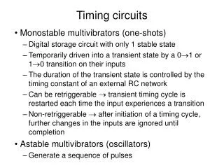
Timing circuits • Monostable multivibrators (one-shots) • Digital storage circuit with only 1 stable state • Temporarily driven into a transient state by a 01 or 10 transition on their inputs • The duration of the transient state is controlled by the timing constant of an external RC network • Can be retriggerable transient timing cycle is restarted each time the input experiences a transition • Non-retriggerable after initiation of a timing cycle, further changes in the inputs are ignored until completion • Astable multivibrators (oscillators) • Generate a sequence of pulses
Timing circuits • The 555 integrated circuit timer • Can be used in both monostable or astable mode, depending on how connected 5V < Vcc <15V Vthreshold > 2/3Vcc resets the RS FF Vtrigger < 1/3Vcc sets the RS FF
Timing circuits • The 555 integrated circuit timer in monostable mode • Stable state: Q=0 (Q’=1), C is discharged (why?) • Pulse U on TRIG sets Q=1 • C charges through RA • Until VC=VTHRESH>2/3VCC • Ignores new TRIG pulsesuntil cycle complete(why?) • Tpulse 1.1RAC
555 in astable mode • Q=1 (Q’=0), C charges through RA+RB • When VC>2/3VCC, the R input ofthe internal FF becomes 1 • The FF flips, Q=0 (Q’=1),transistor Q1 opens,C discharges through RB • When VC<1/3VCC, the S inputof the internal FF becomes 1 • The FF flops, Q=1 (Q’=0),transistor Q1 closes,C charges through RA+RB • tH 0.69(RA+RB)C • tL 0.69RBC • T 0.693(RA+2RB)C
Rapid prototyping of sequential circuits • Use PROMs for the logic • Easy to re-program • Directly implement function • No need to optimize
Rapid prototyping of sequential circuits (c) implementation • (a) State table • (b) PROM truth table
Rapid prototyping of sequential circuits • Prime number sequencer • What should be the contents of the non-prime locations?