Download
1 / 18
180 likes | 297 Vues
Flat Panel Displays --- Principles, Materials and Processes Jing Zhang 04/06/2004. Outline. CRT (Cathode Ray Tube) Displays Flat Panel Displays - Classification; - Liquid Crystal Displays; - Basic Principles; - Addressing Issues; - Modified LCD

E N D
Flat Panel Displays --- Principles, Materials and ProcessesJing Zhang04/06/2004
Outline • CRT (Cathode Ray Tube) Displays • Flat Panel Displays - Classification; - Liquid Crystal Displays; - Basic Principles; - Addressing Issues; - Modified LCD - Field Emission Displays; • Conclusions
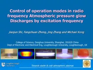
CRT • CRT lives on: 50s – VS EL; 60s – VS Plasma panels; now – VS LCD. • Advantage: Available in a variety of sizes with a wide selection of phosphors; Fast response time; Low cost, etc. • Disadvantage: Depth needed to focus or scan the beam; High power consumption.
CRT Displays – Basic Operations Left: Basic structure of Cathode-ray tube. Right: Addressing method of CRT – Raster.
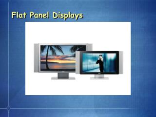
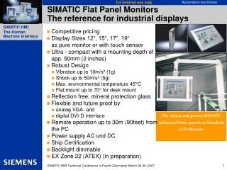
Flat Panel Displays • Flatness Ratio: Depth to picture diagonal • Definition: Flat; Light; Require less power… • Classification: Emissive: Gas discharge; Plasma panel; Light- emitting diode; Vacuum fluorescence; Electroluminescence; Flat cathode-ray tube; Non-emissive: Liquid crystal; Electromechanical; Electrochromatic; Electroactive solids;
Liquid Crystal • Shape & Phases:
Liquid Crystal Displays • Principle of a twisted nematic (TN) LCD • Supertwisted nematic LC cell: Larger twisted angle; Smaller voltage required
Addressing Schemes for LCD Left: Direct Addressing Right: Passive Matrix LCD with row and column electrodes
TFT matrix Addressed LCD • Motivation: To improve the response speed • Circuit & Schemes:
Fabrication of TFTs • TFTs are Metal-Insulator-Semiconductor Field Effect Transistors, which are used more often as bottom-gate. • For gate-dielectric: CdSe – aSi – PolySi • A-Si: Low mask count; Small number of mask alignments and processing steps • P-Si: Higher mobility; but needs to develop low temperature processing.
Guest – Host (GH) Displays • TN & STN: Low transmittance; High power consumption. • GH Displays: Fewer polarizer and color filters; Bright; Wide viewing angle. • Host – Liquid Crystal; Guest – anisotropic dyes
Guest - Host Displays Left: Basic GH cell. Off state: Polarized white light is absorbed by the dye. Remaining spectrum exits as the colored light. On state: Dyes are tuned by electric field and allow the light to pass as white light. Right: Double GH cell. The polarizer is replaced by the second cell, in which the LC molecule orientation is rotated by 90 degree with respect to the first cell.
Guest – Host Displays Left: Reflective GHD. Off state: Dye absorption yields a dark state. On state: Smooth metal electrode reflects almost 100 percent of the incoming light, which is forward scattered by the front scattering film. Right: Structure of a stacked three – layer GHD. It generates color without using a color filter, by relying on the combined absorption of the dyes. This sequence generates largest contrast.
Transflective with VA cells Reflective: If no E field: 2* (Pi/2); If E applied: 2* (Pi/2+Pi/2). Transmissive: If no E field applied: Two WRFs make no retardation, which obtains a dark state; If E applied: Polarization twisted by LC. Lee SH, Do HW, etal. Jpn. J Appl. Phys. Vol. 42 (2003) p1455
Field Emission Displays • Electrons are generated by field emission rather than thermal emission. • Less power consumption and instant turn-on; wide viewing angle; high color saturation. • Sub-micron tips: Low work function material, sharp tips, suitable emitter materials.
FED enabled by nanotubes Wang QH, Yan M, Chang RPH, Applied Physics Letters, 78, p1294 (2001)
FED enabled by nanotubes • Fabrication Process:
Conclusion • Flat panel displays are playing more important roles with increasing quality and decreasing cost; CRT displays still share the display market at the same time. • Mature technology is developed for liquid crystal displays, as well as other flat panel displays. • Performance on power, image quality can be improved.