Measure Thin-film
SemiconSoft, Inc solutions are available for a variety of applications, from desktop and in-situ to in-line measurement. Visit here for more thickness measurement instrument: http://www.semiconsoft.com/wp/products/

Measure Thin-film
E N D
Presentation Transcript
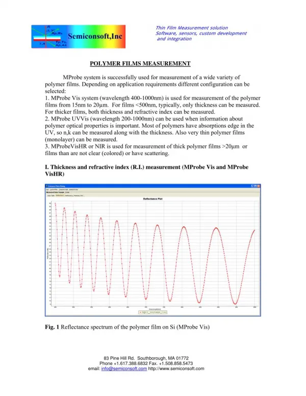
Thin Film Measurement solution Software, sensors, custom development and integration POLYMER FILMS MEASUREMENT MProbe system is successfully used for measurement of a wide variety of polymer films. Depending on application requirements different configuration can be selected: 1. MProbe Vis system (wavelength 400-1000nm) is used for measurement of the polymer films from 15nm to 20µm. For films <500nm, typically, only thickness can be measured. For thicker films, both thickness and refractive index can be measured. 2. MProbe UVVis (wavelength 200-1000nm) can be used when information about polymer optical properties is important. Most of polymers have absorptions edge in the UV, so n,k can be measured along with the thickness. Also very thin polymer films (monolayer) can be measured. 3. MProbeVisHR or NIR is used for measurement of thick polymer films >20μm or films than are not clear (colored) or have scattering. I. Thickness and refractive index (R.I.) measurement (MProbe Vis and MProbe VisHR) Fig. 1 Reflectance spectrum of the polymer film on Si (MProbe Vis) 83 Pine Hill Rd. Southborough, MA 01772 Phone +1.617.388.6832 Fax. +1.508.858.5473 email: info@semiconsoft.com http://www.semiconsoft.com
Fig.2 Using a “thick film algorithm” to estimate the thickness of the films (standard polymer material R.I.~ 1.6 is used) Fig. 3 Using direct fit shows that R.I is not correct – it should be adjusted to have a good fit between measured data and the model. The amplitude of the oscillations is a measure of optical contrast (refractive index difference) between two materials of the interface. 83 Pine Hill Rd. Southborough, MA 01772 Phone +1.617.388.6832 Fax. +1.508.858.5473 email: info@semiconsoft.com http://www.semiconsoft.com
Fig. 4 Fit of thickness and R.I. gives better result. Fig.5. R.I. spectrum determined from the measurement 83 Pine Hill Rd. Southborough, MA 01772 Phone +1.617.388.6832 Fax. +1.508.858.5473 email: info@semiconsoft.com http://www.semiconsoft.com
Fig. 6 Measurement of thick polymer on thin glass (1.3mm) using MProbe VisHR. Large mismatch between the measurement and the model shows that refractive index of the polymer is not correct. Optical contrast between glass and polymer is much higher i.e. polymer’ R.I. should be higher. Fig. 7 Polymer refractive index is adjusted to fit the measured data. The difference in R.I. between Fig. 6 (R.I.=1.582)and Fig. 7(R.I.=1.667) is ~0.08 Precision of R.I.<0.001 (1 σ) can be achieved. 83 Pine Hill Rd. Southborough, MA 01772 Phone +1.617.388.6832 Fax. +1.508.858.5473 email: info@semiconsoft.com http://www.semiconsoft.com
II. Measurement of a thick polymer films Fig. 8 Reflectance spectrum of the a free-standing polymer film with polymer coating Fig.9. Thicknesses of both layers can be easily determined using thick-film algorithm as 21.8 um and 2.1um (thicknesses are indicated by position of the peaks) 83 Pine Hill Rd. Southborough, MA 01772 Phone +1.617.388.6832 Fax. +1.508.858.5473 email: info@semiconsoft.com http://www.semiconsoft.com
III. Measurement of polymer films of PET substrate (touch-screen application) Fig. 10 Measurement of the PET sample with primer and main polymer layer (35nm primer, 85nm additional polymer layer). Model to measured data fit. The “noise” in spectrum due to the effect of the thin PET substrate. PET n,k were determined from measurement of the blank PET sample. 83 Pine Hill Rd. Southborough, MA 01772 Phone +1.617.388.6832 Fax. +1.508.858.5473 email: info@semiconsoft.com http://www.semiconsoft.com
Fig.11 Measurement of the PET sample with primer. Fig, 12. Primer R.I spectrum determine from the measurement. 83 Pine Hill Rd. Southborough, MA 01772 Phone +1.617.388.6832 Fax. +1.508.858.5473 email: info@semiconsoft.com http://www.semiconsoft.com
IV. Measurement polymers on flexible printed board (MProbe VisHR) Fig. 13 Reflectance spectrum at 2 points on the printed board showing that at least 2 films are present Fig.14. Results of the spectrum analysis. 1.2µm polymer film (peak 1 ), 84 µm PET (peak 2). Peak 3 is a total thickness PET+polymer (85.2 µm) 83 Pine Hill Rd. Southborough, MA 01772 Phone +1.617.388.6832 Fax. +1.508.858.5473 email: info@semiconsoft.com http://www.semiconsoft.com
V. Conductive polymer layer on PET (MProbe Vis) Fig. 15. Conductive polymer layer on PET substrate (Model vs. measurement). Thickness: 853nm Fig. 16 Optical constants of conductive polymer determined form the measurement. 83 Pine Hill Rd. Southborough, MA 01772 Phone +1.617.388.6832 Fax. +1.508.858.5473 email: info@semiconsoft.com http://www.semiconsoft.com
VI. Measurement of biopolymer coating on implant stent. Fig. 17 Biopolymer film on Ti stent. Model vs. measurement. Film thickness: 97nm Fig. 18. Optical constants of the polymer film determined form the measurement. 83 Pine Hill Rd. Southborough, MA 01772 Phone +1.617.388.6832 Fax. +1.508.858.5473 email: info@semiconsoft.com http://www.semiconsoft.com
VII. Polymer film measurement - optical constants analysis (MProbe UVVis) Fig. 19. Measurement of polymer with squaraine dye deposited on glass. Model vs. measured data. Thickness 41nm Fig. 20. Optical constants of the polymer determined from the measurement. 83 Pine Hill Rd. Southborough, MA 01772 Phone +1.617.388.6832 Fax. +1.508.858.5473 email: info@semiconsoft.com http://www.semiconsoft.com
VIII. Measurement of thin polymers (MProbe UVVis) Fig, 21 Reflectance spectra of gold (uncoated), 1.3nm polymer/gold, 2.6nm polymer/ gold. Polymer monolayer can be easily distinguished and measured. Fig. 22. Measurement of the polymer monolayer (1.3nm). Model vs. measurement. 83 Pine Hill Rd. Southborough, MA 01772 Phone +1.617.388.6832 Fax. +1.508.858.5473 email: info@semiconsoft.com http://www.semiconsoft.com