Download
1 / 35
350 likes | 485 Vues
A Building Block Approach to Sensornet Systems. Prabal Dutta, Jay Taneja, Jaein Jeong, Xiaofan Jiang, and David Culler. UC Berkeley Sensys 2008. Presenter: SY (some slides borrowed from Dutta). (Wireless) embedded systems are tightly coupled to the application. Common Computation

E N D
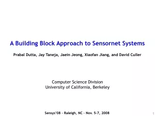
A Building Block Approach to Sensornet Systems Prabal Dutta, Jay Taneja, Jaein Jeong, Xiaofan Jiang, and David Culler UC Berkeley Sensys 2008 Presenter: SY (some slides borrowed from Dutta)
(Wireless) embedded systems are tightly coupled to the application • Common • Computation • Communication • Storage • Application-specific • Power • Sensing • Mechanical PEG [Sharp05] HydroWatch [Taneja07] Redwoods [Tolle05] Shimmer [Intel06] PicoCube [Chee08] Radar [Dutta06]
Serious applications go through three stages Production “Reducing cost” “Optimizing performance” “Improving manufacturability” “Obtaining high reliability” “Finalizing mechanicals” Prototype Goal: “Try it and see” “Rapid prototyping” Pilot Goal: “Unprecedented data” “Realistic study” “Modest scale” “Modest investment” “Well-enough executed” + Accrue Learnings Artifacts Investments =
Epic design philosophy • Consolidate deep expertise into reusable modules • Integrate modules with simple glue • 3 P’s : Prototype, Pilot, Production
Outline • Introduction • Related Work: Building the design rules • Design Rules • Building Blocks and Development Stages • Modules • Results • Revisiting the Design Rules • Conclusion
Modular platforms and plug-and-play development PC/104 [Cerpa01] PASTA [Bajura05] Mica [Hill01] Mica2 [Xbow03] MicaZ [Xbow05] Rene [Hill99] WeC [Hill98] Stargate [Intel] WINSng [Pottie00] WINS [Rockwell] mPlatform[Lymberopoulos07]
Some (inconvenient) truths about these modular approaches • Prototyping is simple…plug-and-play • Unspecified “faux busses” can result in signal conflicts • Multiplexed busses can avoid conflicts • They present barriers to simple interfacing • Lego-like snap together modularity is great • Backplanes and board stacks • Too Bulky • Waste space • Expensive relative to other components • Too fragile for experimentation and pilots (max insertions) • Force 3D board packaging geometry • 51-pin connector is ubiquitous! • Instead of being “just right” • Often too general for simple applications • And too limited for demanding ones
Building the design rules • Modularity… • Really hard stuff must be reused unchanged • Snap/plug together • Good for prototyping…bad for production • Generic bus/backplane • Expensive, fragile, and often gets in the way
OPPOSITE VIEW: THE HIGHLY-INTEGRATED APPROACH Telos/Tmote [Polastre05] PC/104 [Cerpa01] PASTA [Bajura05] Mica [Hill01] Mica2 [Xbow03] MicaZ [Xbow05] Rene [Hill99] WeC [Hill98] Stargate [Intel] WINSng [Pottie00] WINS [Rockwell] mPlatform[Lymberopoulos07]
Some (inconvenient) truths about thehighly-integrated approach • Bundles core, sensors, antenna, power, host interface, and expansion port • Onboard sensors make great demos • Onboard sensors complicate the mechanicals • Some sensors don’t make sense: TSR/PAR next to Temp/Hum • Integrated USB host interface makes software development easy • Integrated USB host interface adds cost and goes unused in production • IDC expansion slot • Forces 3D board stacking or cabling • Realistic pilots strained because too few I/O are exposed • Integrated power with battery/host cutover • Hard to intercept power lines for measurement or debugging
Building the design rules • Modularity is good • Snap/plug together • Eliminate bus/backplane • Export everything • Don’t limit generality • Partition functionality • Eliminate waste • Remove the sensors • They’re application-specific • Separate the power supply • It’s application-specific • Make current measurements easy
Emerging commercial platforms are designed for manufacturability Tmote Mini [Sentilla07] Telos/Tmote [Polastre05] PC/104 [Cerpa01] PASTA [Bajura05] Mica [Hill01] Mica2 [Xbow03] MicaZ [Xbow05] Iris [Xbow07] Rene [Hill99] WeC [Hill98] Iris OEM [Xbow07] MicaZ Stamp [Xbow06] Stargate [Intel] WINSng [Pottie00] WINS [Rockwell] mPlatform[Lymberopoulos07]
Some (inconvenient) truths about theproduction-quality, assembly-optimized modules • Excellent radio performance • Might still require RF engineering • Ideal for high-volume, pick-and-place assembly • Hard to socket or hand-solder for prototype and pilot studies • Hard to probe I/O lines for debugging • Narrow interface makes integration easy • Hides many internal signals useful for research
Design rules for application-specific platform development • Modularity is good • Snap/plug together • Eliminate bus/backplane • Export everything • Partition functionality • Remove the sensors • Separate the power supply • Performance at worst -suboptimal • RF out-of-the box • Socketable • Hand-solderable
Design Rules redux Epic Building Block design rules • Modularity is good • Snap/plug together • Eliminate bus • Export everything • Partition functionality • Remove the sensors • Split power supply • Only -suboptimal • RF out-of-the box • Socketable • Hand-solderable • Partition functionality • Export wide electrical interface • Eliminate the system bus • Modules at worst -suboptimal • Support many physical interconnects
Epic building block approach to supportprototype, pilot, and production • Two architectural elements • Module • Carrier • Module • General-purpose subsystem • Reusable, self-contained • Multi-chip module package • Composed of one or more ICs and discrete components • Carrier • Application-specific glue • Glues together • General-purpose modules • Application-specific sensors, power supplies, mechanicals
Epic building block approach: a concrete example Core USB Storage Start with modules Incorporate with carriers Create platforms Prototype Production Pilot • Teaching/Experimentation • Sensors: via connectors • Power: USB, Li+, Alkaline • Mechanical: All I/O exposed • Research/Measurement • Sensors: temp/hum/light • Power: USB, Alkaline • Mechanical: Telos-like • Scientific/Application • Sensors: V/I/temp • Power: AC, USB • Mechanical: Wall plug
Outline • Introduction • Related Work: Building the design rules • Design Rules • Building Blocks and Development Stages • Modules • Results • Prototype • From Pilot to Production • Organic Reuse • Revisiting the Design Rules • Conclusion
CORE MODULE • a wireless sensornet node (mote) core that integrates a microcontroller, radio, and flash memory. • Most critical, and difficult part • A bunch of chips available • How to choose
MICROCONTROLLER -- CRITERIA • Low currents • Low operating voltage • Fast wakeup • Sufficient RAM and Flash • 16-bit timer • DMA
RADIO -- CRITERIA • Idle listen current • Sleep current and wakeup time • Link budget
SELECTION REVISIT • MSP430F1611 + CC2420, still hold? • Yes • They are still competitive • If re-design now, still use same chips? • No • MSP430F26x or MSP430F54x + CC2520 • Cost of re-design core module is very high
OTHER MODULES • Storage Module • 1 Gbit NAND flash • two 16 Mbit NOR flash • 512 Kbit FRAM • USB Module • Host interface • Reprogramming • JTAG over USB • Battery management
Outline • Introduction • Related Work: Building the design rules • Design Rules • Building Blocks and Development Stages • Modules • Results • Prototype • From Pilot to Production • Organic Reuse • Revisiting the Design Rules • Conclusion
Prototyping: experimentation and debugging Development Board Interface Board Breakout Board Interface Board Phidgets
Result: Five application-specific platforms in six months with five grad students HydroWatch Benchmark ACme Jiang Jeong, Taneja Dutta PowerNet (Stanford) Meraki Daughterboard Quanto Testbed Dutta, Goto Dutta Gal, Heller, Kazandjieva
Carriers: gluing together module with app-specific sensors, power supplies, and mechanicals ACme AC Meter & Ctrl HydroWatch Environmental Mon. Benchmark Testbed measurement Meraki Daughterboard b6lowpan border router 1. Modules: Core 2. Sensors: T/H/L 3. Power: Solar, NiMH 4. Mech: NEMA 4 encl 5. PCB: 2-layer 6. Design: 2 days 7. $10.83 ea @ 60 pcs 8. Fab Leadtime: 5-day 1. Modules: Core 2. Sensors: V, I 3. Power: AC 4. Mech: enclosure 5. PCB: 2-layer 6. Design: 1 week 7. $26.40 ea @ 5 pcs 8. Fab leadtime: 5-day 1. Modules: Core, USB 2. Sensors: E/T/H/L 3. Power: USB 4. Mech: Telos-like 5. PCB: 4-layer 6. Design: 3 days 7. $141.30 ea @ 10 pcs 8. Fab leadtime: 5-day 1. Modules: Core 2. Sensors: T/H 3. Power: Meraki 4. Mech: Meraki 5. PCB: 2-layer 6. Design: 5 hours 7. $33 ea @ 6 pcs 8. Fab leadtime 5-day All first articles were hand-assembled in hours. Shortens platform development time-to-result. Makes custom platforms broadly accessible.
Approach promotes reuse in modules, CAD parts, inventory, subsystems
Outline • Introduction • Related Work • Design Rules • Building Blocks and Development Stages • Modules • Results • Revisiting the Design Rules • Conclusion
The design rules • Partition functionality • Export wide electrical interface • Eliminate the system bus/backplane • Modules at worst -suboptimal • Support many physical interconnects
Where do modules come from?Heuristics for partitioning functionality If the answer to any of these questions is yes, then make it a module. Otherwise, it’s a carrier board.
2 MSP430F1611 CC2420 DVDD AVDD AGND OSC P4.1 SFD RVDD P1.4 CCA 4 ATEST1 P1 / GPIO P1.3 FIFO ATEST2 5 P1.0 FIFOP P2 / GPIO RFRXTX 2 4 P4.5/P4.6 P3 / USART / GPIO ENA/RST RFOUT RFGND(2) 3 4 P4 / GPIO [LED(3)] P3/SPI0 SPI U.FL 8 P5 / GPIO AT45DB161D 8 4 P5/SPI1 SPI FVDD P6 / ADC / DAC / GPIO WP VREF+ P1.7 RST VeREF+ DS2411 VeREF- JTAG OSC RST P2.4 ONEWIRE 4 2 LCC-68 PAD FRAME EXPORT A WIDE ELECTRICAL INTERFACE…ACTUALLY, JUST EXPORT EVERYTHING (ALMOST)
Modules can be only –suboptimalif they are to be enthusiastically adopted
Support many physical interconnect options Prototype “Routed Vias” 1. Free connector 2. Easy to solder 3. Easy to probe 4. Connect all layers Pilot Socketing Production Hand Soldering Hardware Inlining LCC-68 footprint
Conclusion TinyOS 2.1 support: Make epic install [miniprog] Oct’08 Jan’08 • Near-optimal platform decomposition • From “try it and see” to high-volume production • Enables rapid platform development through reusable carriers, modules, and CAD parts • Epic is Open Source Hardware • CAD source, gerbers, BOM available online • Share you CAD parts and board designs! http://www.cs.berkeley.edu/~prabal/projects/epic PowerNet (Stanford)