Design of Reinforcement for Concrete Plates: Lecture on Normal Forces and Moment Requirements
This lecture covers the analysis and design of reinforcement in concrete plates, focusing on normal forces and moment capacities. It discusses equilibrium conditions, reinforcement requirements based on examples, and methods to minimize reinforcement while ensuring structural safety. Various design approaches and examples, including handling point loads and torsion, are provided to illustrate the concepts. Emphasis is placed on linear elastic analysis for establishing force flows, followed by plastic dimensioning for optimal designs.

Design of Reinforcement for Concrete Plates: Lecture on Normal Forces and Moment Requirements
E N D
Presentation Transcript
Reinforcement for Plates Course CT4150 Lecture12 5 Jan. 2010
Normal forces in concrete plates • Only rebars in the x and y directions • Equilibrium of a plate part
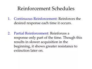
Equations • Design Choose q such that nsx+nsy is minimal (lower bound theorem)
Example 1 • Situation nxx=1200, nyy=-200, nxy=-400 kN/m fy = 500 N/mm², f’c= 30 N/mm² Thickness = 100 mm • Reinforcement nsx= 1200+400 = 1600 kN/m nsy= -200+400 = 200 • Concrete nc= -2x400 = -800 kN/m
Asx=1600/500 = 3.20 mm = 3200 mm²/m 212–280 = 2p/4x12²x1000/280 = 3231 OK Asy=200/500 = 0.40 mm = 400 mm²/m 26–500 = 2p/4x6²x1000/500 = 452 OK sc= 800/100 = 8 N/mm² < f’c OK (safety factors omitted)
Example 2 • Deep beam 4.7x7.5 m, 2 supports, opening 1.5x1.5 m, point load 3000 kN, fcd = 16.67 N/mm², fyd = 435 N/mm²
Forces nxx, nyy, nxy (linear elastic analysis) • Principal stresses
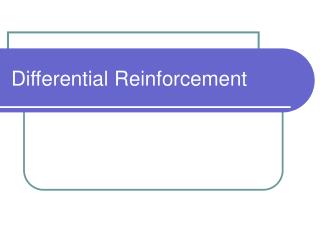
Moments in concrete plates • Only rebars in the x and y directions • Equilibrium of a plate part • Result (Yield contour)
Example 3 • Moments in a point mxx = 13, myy = -8, mxy = 5 kNm/m • Moment capacities mpx = 17, mpy = 0, m’px =0, m’py = 10 • Is the capacity sufficient? • Yes
Design of moment reinforcement • Carry the moments with the least amount of reinforcement. • So, minimize mpx+ mpy+ m’px+ m’py • 5 constraints • mpx, mpy, m’px, m’py≥ 0 Solution 1 (Wood-Armer moments) • Crack direction 45º to the reinforcing bars
Solution 2 (when mpx would be < 0) Solution 3 (when mpy would be < 0)
Solution 4 (when m’px would be < 0) Solution 5 (when m’py would be < 0)
Solution 6 (when mpx and mpy would be < 0) Solution 7 (when m’px and m’py would be < 0)
Example 4 • Moments in a point (as in example 1) mxx = 13, myy = -8, mxy = 5 kNm/m • Moment capacities mpx = 13+5²/8 = 16.13 m’px = 0 mpy = 0 m’py = 8+5²/13 = 9.92 • Amount of reinforcement is proportional to 16.13+0+0+9.92 = 26 • Amount of reinforcement in example 3 17+0+0+10 = 27 (larger, so not optimal)
Example 5 • Plate bridge, simply supported • 4 x 8 m, point load 80 kN, thick 0.25 m
Example 5 continued • Decomposition of the load
Example 5 All moments • Moments in the bridge middle • Moments at the bridge support
Example 5 Reinforcement Middle Support Designed
Example 5 Upper bound check Result > 1 OK
Conclusions The design procedure used is 1 Compute the force flow linear elastically 2 Choose the dimensions plastically The reason for the linear elastic analysis in the first step is that it shows us how an as yet imperfect design can be improved. A plastic (or nonlinear) analysis in step 1 would shows us how the structure would collapse; but that is not what we want to know in design. This procedure is applied to design many types of structure for the ULS.