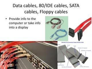
SCTA Test Setup Enhancements and Signal Analysis in Long Cables
This report details the upgrades and findings from the SCTA test setup at the Liverpool VELO Workshop. Key enhancements included relocating hardware to VELOLAB, improving the TTC chip with a soft reset, and implementing a shared clock across all boards. Various cable lengths were tested, examining the effects of line equalizers and short vs. long cable performance. Signal integrity issues, noise pickup, and linearity were critically analyzed, establishing the relationship between signal-to-noise ratios and various configurations. Data indicate challenges with long cables but confirm the feasibility of reading data reliably.

SCTA Test Setup Enhancements and Signal Analysis in Long Cables
E N D
Presentation Transcript
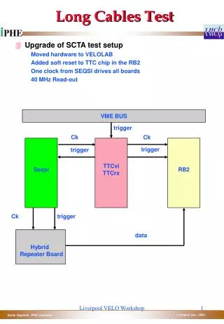
Long Cables Test • Upgrade of SCTA test setup • Moved hardware to VELOLAB • Added soft reset to TTC chip in the RB2 • One clock from SEQSI drives all boards • 40 MHz Read-out VME BUS trigger Ck Ck Seqsi TTCvi TTCrx RB2 trigger trigger Ck trigger Hybrid Repeater Board data Liverpool VELO Workshop
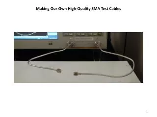
SCTA data read-out Short cable • 2 chip daisy chain read hybrid • “short cable” readout without the Line Equalizer • Probing the signal before the ADC Repeater Board FADC + RB2 No Line Equalizer ~50 cm ~30 cm Patch box Flat cable Bipolar Lemo Liverpool VELO Workshop
SCTA data read-out Short cable • Deformed header @ 40 MHz • 1 MIP injected Liverpool VELO Workshop
SCTA data read-out Long cable no equalizer • 60 m cable (see Raymond talk) between the Repeater Board and the ADC • No attempt to recover the signal Liverpool VELO Workshop
SCTA data read-out Long cable • 60 m cable • Line equalizer • Standalone FADC outside of the RB2 60 m Repeater Board Standalone FADC Line Equalizer ~50 cm ~30 cm Patch Panel Patch Panel Pair of Lemo Bipolar Lemo Liverpool VELO Workshop
SCTA data read-out Long cable • Deformed Header - Repeater Board drivers are too weak • RC behavior after the header (line mismatch?) Liverpool VELO Workshop
SCTA data read-out Long cable • Added a buffer stage before the cable • Same drivers used in the Raymond tests • Header fully recovered - Amplifier chain gain ~ 0.5 ~50 cm 60m Repeater Board Standalone FADC LineEqualizer ~30 cm Line Drivers Patch Panel Patch Panel Pair of Lemo Bipolar Lemo Liverpool VELO Workshop
SCTA data read-out Long cable + RB2 • Inserted the FADC into the RB2 • Pick up of noise when inserted into RB2 ~50 cm 60m Repeater Board FADC + RB2 LineEqualizer ~30 cm Line Drivers Patch Panel Patch Panel Pair of Lemo Bipolar Lemo Line Drivers FADC Input Liverpool VELO Workshop
SCTA data read-out Long cable + RB2 • Data seen in the Oscilloscope Line Drivers FADC Input FADC Input Averaged FADC Input Liverpool VELO Workshop
SCTA read-outRB2 Pedestal • Check the effect of high frequency noise Delay scan • The RB2 has one 5 bit PDU with 1 ns time resolution • Not all the delay settings are allowed • Delay between the RB2 FPGA input register and the FADC • Writing to FIFO a non stable FADC value Injected charge scan • Up to 1 MIP injected charge Signal to noise ratio, linearity and significance • The signal to noise ratio is (<signal> - pedestal) / noise • Significance is defined as signal / sigma(signal) and gives an hint of how stable are the signals Liverpool VELO Workshop
SCTA read-outRB2 • Pedestal plots are sensible • The pedestal sigma is greater • The noise is as usual Liverpool VELO Workshop
SCTA read-outRB2 - Short cable • ADC value vs. PDU delay for half a Mip and 1 Mip injected for one “typical” channel • FADC data instability? Liverpool VELO Workshop
SCTA read-out RB2 - Short cable • Signal linearity is good once you selected the proper time slot Liverpool VELO Workshop
SCTA read-out RB2 - Short cable • Signal to noise ratio The signal significance is greater than 10 over more than 10 ns Liverpool VELO Workshop
SCTA read-outRB2 - long cable • ADC value vs. PDU delay for (about) half a Mip and 1 Mip injected Liverpool VELO Workshop
SCTA read-out RB2 - Long cable • Signal linearity is like expected from SCTA • Cross check that data are sensible Liverpool VELO Workshop
SCTA read-out RB2 - Long cable • The signal to noise ratio is 10% less than the one measured with the short cable • gain uncertainty - linearity The signal significance is good over ~ 15 ns The signal slope is significant Liverpool VELO Workshop
Conclusions • First measurements of SCTA at 40 MHz highlighted some limits of the system • Weak line driver in the repeater board • Pick up noise into the RB2 • RC behavior • Reduced PDU delay range • The showed results are “typical”… Some problems with many channels, PDU delays, timing of the system indeed. • Some check still to do • Data are there, however • It is possible to read data with long cables • The chosen cable is not the best on the market... • The line equalizer can be even better optimized • End of exercise • Cross talk • Signal to noise for a particle (laser) • Resolution (difficult to do without a beam…) Liverpool VELO Workshop