High Speed Electrical Data Transmission on Long Flex Cables
250 likes | 476 Vues
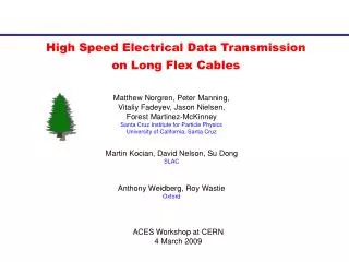
High Speed Electrical Data Transmission on Long Flex Cables. Matthew Norgren, Peter Manning, Vitaliy Fadeyev, Jason Nielsen, Forest Martinez-McKinney Santa Cruz Institute for Particle Physics University of California, Santa Cruz. Martin Kocian, David Nelson, Su Dong SLAC.

High Speed Electrical Data Transmission on Long Flex Cables
E N D
Presentation Transcript
High Speed Electrical Data Transmissionon Long Flex Cables Matthew Norgren, Peter Manning, Vitaliy Fadeyev, Jason Nielsen, Forest Martinez-McKinney Santa Cruz Institute for Particle Physics University of California, Santa Cruz Martin Kocian, David Nelson, Su Dong SLAC Anthony Weidberg, Roy Wastie Oxford ACES Workshop at CERN 4 March 2009
Outline • Introduction • Tools • Impedance assessments • Point-to-Point links • Driving parallel lines • Conclusions V. Fadeyev (UCSC)
Introduction • A low-mass embedded flexible cable is a natural choice in stave-like concepts being developed in ATLAS to transmit the data from individual modules to the end for aggregation/readout. • Investigating LVDS signal transmission on flex cable striplines of ~0.5-1m long at speeds of up to 320 Mbps. • Assuming point-to-point links between hybrids and stave controller for data coming from the detector, at 160 or 320 MHz. • Multi-tap clock/com lines run at likely lower speed. V. Fadeyev (UCSC)
Prototype Stave Cables Made connections for point-to-point links of up to 1 m long and the last group of 10 clock connections (parallel) • A version of ATLAS strip stave’s prototype cable from Carl Haber at use at UCSC. • 1 meter long • Hybrid locations (taps) every 3.3 cm A similar cable (1.2 m, 24 taps, on carbon fibre) is built at Oxford for further prototyping. Use oscilloscopes and FPGAs for eye diagrams and bit error rate measurements. V. Fadeyev (UCSC)
Impedance • Geometry: 4 mill width, separation, 0.7 mill height, 2 mill of dielectric to metal layers. • Impedance calculation • 56 Ohm . This is somewhat idealized model. In reality is more complicated, with a glue layer etc. Will test with 50 and 75 Ohm terminations. Al adhesive kapton double-sticky tape Cu V. Fadeyev (UCSC)
TDR scope plots Clear reflections with 75 Ohms. Z ~ 30 to 50 Ohms (single ended) Impedance tests on the Oxford cable (does not have to be exactly the same as for previous cable). V. Fadeyev (UCSC)
Point-to-Point Links V. Fadeyev (UCSC)
ED on point-to-point links at 160 MHz 50 Ohm 75 Ohm LVDS is a current source standard => Amplitude = 3.5 mA x Termination ~1m Data30 ~50cm Data18 ~10cm Data03
Transitions At the driver After 1m long trace See a small-scale irregularity, and a slow leveling off after transition. The irregularity is likely to be a property of the driver (SN65LVDS100). The slow transition is a property of the line (next slide). V. Fadeyev (UCSC)
Simulations D = 0.002, 0.02 D = 0.2 HyperLynx, one of the industry-standard packages from Mentor Graphics. 2D Field solver, works off a PCB/cable layout. Simulated with loss tangent D = 0.002, 0.02 (standard for FR4), 0.2. Only see a significant difference in the latter (extreme) case. => Most of the “slow rise” effect due to Skin effect? V. Fadeyev (UCSC)
ED tests with extra capacitance @160 MHz 50 Ohm 75 Ohm C = 0 pF C = 20 pF @ source C = 20 pF @ Termination
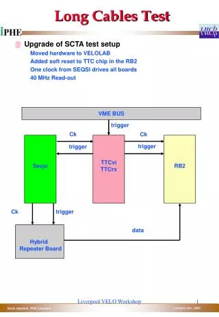
Transmission test at 320 MHz SN65LVDS100 SN65LVDS100 LVDS buffer LVDS buffer Flex cable FPGA D R Twisted pair for return signal Error out Error out Cable is enclosed between LVDS buffers to limit the effect of other connections. V. Fadeyev (UCSC)
“Bathtub” Curve for Data Links • Error rate as a function of clock phase. • See a working region of ~2.5 ns with 4.16x10^9 samples. • No significant change in performance with C = 10 pF at either • source or termination end. Error rate measurement Simulation ED V. Fadeyev (UCSC)
IBL Data Transmission using the ATPIX Transceiver Chip • Test-up includes: • Xilinx ML-405 development board • Random pattern test code Martin Kocian • ATPIX LVDS test chip • Two PPA-0 flex circuits – 50 cm • One HRS connector • One – 4 meter twisted pair 36 AWG wire • 160 Mbps data rate • Eye pattern is 317mV, need > 200mV • Cross talk measurement OK • We should consider MLVDS receivers • Eye requirement is 100mV • No errors @ 150 Mbps or 350 Mbps • Error rate better than 2*10-13 @ 350 Mbps SLAC test of data transmission through 50 cm flex + 4 m twisted pair. V. Fadeyev (UCSC)
Driving Parallel Connections V. Fadeyev (UCSC)
Eye Diagrams at 80 MHz Middle Termination (75 Ohm) Source Eye diagrams on Oxford cable (L=1.2m) with 24 x DS91D180 (M-LVDS receivers with C = ~2.5 pF). V. Fadeyev (UCSC)
BERT and Jitter at 80 MHz At termination (75 Ohm) At Source BERT and jitter measurements on Oxford cable (L=1.2m) with 24 x DS91D180 (M-LVDS receivers with C = ~2.5 pF). V. Fadeyev (UCSC)
Parallel loading of multiple receivers @160 MHz 75 Ohm 10 x 0 pF 10 x 2 pF 10 x 6 pF Tap9 furtherst Tap5 middle Tap0 term
Parallel loading of multiple receivers @160 MHz 50 Ohm 10 x 0 pF 10 x 2 pF 10 x 6 pF Tap9 furthest Tap5 middle Tap0 term.
Conclusions • Data transmission on point-to-point links is ok at 320 MHz. Extra capacitance of 10 pF does not deteriorate the performance. A combination of flex cable + long twisted pair works as well. • Driving a group of parallel loads looks possible at 160 MHz when each load is ~few pF. Verified at 80 MHz with commercial receivers with C = 2.5 pF. • Have a simulation tool that could be useful with cable design and engineering. • Work is in progress, more system-level testing to be done. V. Fadeyev (UCSC)
Backup Slides V. Fadeyev (UCSC)
BERT Development • Got a firmware error-counting design at 320 MHz with Virtex-5 FPGA board to work. • An option to scan the phase of in-coming data latch to find the working phase margin and amount of jitter in the system. • “Raw” bit error counting from PRBS: • No packets/framing. • No DC-balancing (8/10 or 64/66 or else) encoding • No pre/de-emphasis on LVDS lines. V. Fadeyev (UCSC)
Effect of Multiple trace bends PRBS data (320 MHz) after longest “clock” trace of the long cable. PRBS data (320 MHz) after longest “dataout” trace of the long cable. 15 x 30 x V. Fadeyev (UCSC)
Cross-Talk Drive differential pair with 100 MHz clock (blue) Measure cross-talk signal on adjacent terminated trace (orange) separated by 100 microns (same as stripline width) At source end At termination end Note different scales: cross-talk amplitude is less than 5% . V. Fadeyev (UCSC)
“Bathtub” Curves for Parallel Loads • Our LVDS buffers have built-in 100 Ohm termination => • Can only look at the error rate on the last tap. • Do scans for no C loads, and 2, 4, …, 10 loads of 2 pF. • The working region contracts from ~ 5.0 ns to 4.5 ns. V. Fadeyev (UCSC)